ALUMINUM
QUALITY CONTROL


INTRODUCTION
Symbol: Al
Atomique n°: 13
Density: 2,7
Molar mass: 27 g.mol-1
Melting point: 660 °C
Aluminum is manufactured in several stages:
• First of all there is the extraction of the Bauxite ore (contains 60% aluminum oxide Al2O3, 20-30% iron oxide Fe2O3 and silicon oxide SiO2 and titanium oxide TiO2 in smaller quantities).
• The bauxite is then transformed into alumina using caustic soda, at high temperature and under high pressure.
• The previously-alumina obtained is dissolved in a cryolite bath, and an electric current is passed through the tank. This operation, known as electrolysis, allows aluminum to be collected at the cathode.

Fig 1: Aluminum processing
Alloying elements are used to improve aluminum’s properties:
• Magnesium improves corrosion resistance
• Silicon increases the malleability of the alloy in the foundry
• Copper hardens aluminum
• Zinc and manganese are also key additional elements in the production of aluminum alloys
There are two main families of aluminum:
The most commonly-used name for wrought aluminum is a 4-digit reference (NF EN 573-1), preceded by EN AW.
The first digit determines the alloy group to which the aluminum belongs.
The 2nd digit for group 1 corresponds to any impurities contained in the aluminum.
The 2nd digit for the other groups corresponds to changes in the alloy’s chemical composition.
The 3rd and 4th digits for group 1 alloys depict the percentage above 99% and for the other groups, to identify an alloy in its group.
Example: EN AW – 2024 is an aluminum alloy with 4% copper and 1.5% magnesium.
(The W (wrought) refers to a wrought alloy).
| Group | Aluminum or Alloy |
| 1 | Aluminum (content ≥ 99.00%) |
| 2 | Aluminum – copper |
| 3 | Aluminum – manganese |
| 4 | Aluminum – silicon |
| 5 | Aluminum – magnesium |
| 6 | Aluminum – magnesium-silicon |
| 7 | Aluminum – zinc |
| 8 | Other aluminum alloys |
Table 1: Aluminum alloy groups
The foundry aluminum name refers to the NF EN 1780-1, -2 and -3 standards.
The numerical identification is a series of 5 digits, the first of which refers to table 1 of wrought alloys. The last 3 digits depict the chemical.
The symbolic identification includes chemical symbols of the alloy additions and their respective mass contents after the letters EN AC (C corresponding to «cast» for cast alloy).
In the previous example this gives: EN AC – AlSi7Mg
Finally, standard NF EN 1706 indicates the chemical composition limit of each alloy as well as the mechanical characteristics of these cast alloys.
SURFACE TREATMENTS OF ALUMINUM

Some aluminum alloys have been specially developed for this treatment and anodization thickness can range from 5-50μm.
This surface treatment improves corrosion resistance and is also used for aesthetic purposes.
BENEFITS AND APPLICATIONS OF ALUMINUM AND ITS ALLOYS
• Mechanical resistance: this is improved by the addition of alloy additions to the aluminum.
• Corrosion resistance: a layer of oxides forms naturally on aluminum and protects it from corrosion. The anodizing surface treatment can further improve corrosion resistance.
• Very good thermal and electrical conductivity: this is why aluminum is often used for heat dissipation applications. The electrical conductivity of aluminum is 65% of that of copper.
• Lightness: particularly appreciated in aerospace and aeronautics, this characteristic is very important in these fields.
• LImpermeability: aluminum does not allow light, odours or micro-organisms to pass through. This is why it is used for food and pharmaceutical packaging.

Aluminum is used in aerospace construction and the automotive industry.

Aluminum is also widely used in the food and pharmaceutical industries.

In the building sector, aluminum is widely used for the manufacture of windows, bay windows, profiles on external facades, etc.
METALLOGRAPHIC PREPARATION
• Standardisation of the geometry of the sample taken (if necessary), called «MOUNTING».
• Improvement of the surface condition of this sample, called «POLISHING».
• Sample characterisation: to reveal the microstructure of the sample by an etching reagent (if necessary) called «METALLOGRAPHIC ETCHING» and microscopic observation (optical or electronic).

CUTTING
PRESI’s wide range of medium and large capacity cutting and micro-cutting machines can be adapted to any need with regard to cutting precision, sizing or quantity of products to be cut:


Fig. 4: Turbo clamping – EVO 400

Fig. 5: Intercooler clamping – ST310

Fig. 6: Profile clamping – T330

Fig. 7: Turning part clamping – T210
In the previous figures, different clamps are used depending on the geometry of the parts to be cut. In the present cases, Kopal clamps and quick-action vices were used. All of these clamping means can be adapted to the various cutting machines (in the examples above: Mecatome ST310, EVO 400 and Mecatome T330 or Mecatome T210).
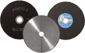
CONSUMABLES
 |
ALUMINUM AND ITS ALLOYS |
| Micro-cutting | MNF UTW S (Ø 180 mm) C |
| Medium-capacity cutting | MNF |
| High-capacity cutting | MNF |
Table 2: Choosing the right cut-off wheel type

MOUNTING
Achieving good-quality mounting is essential to protect fragile materials and also to achieve good preparation results for polishing and future analysis.
Before mounting, the specimen should be deburred with coarse abrasive paper, for example, to remove any cutting burrs. Cleaning with ethanol (in an ultrasonic tank for even greater efficiency) is also possible. This allows the resin to adhere as well as possible to the sample and thus limits shrinkage (space between the resin and the sample).
If shrinkage persists, it can lead to problems during polishing. Abrasive grains may become lodged in this space and then be released at a later stage, thus creating a risk of pollution for the sample and the polishing surface. In this case, cleaning with an ultrasonic cleaner between each step is recommended.
There are two mounting options:
HOT MOUNTING
• Fully automatic hot-mounting press.
• Easy to use: memorisation, adjustment of processes and speed of execution make it a high-precision machine,
• The hot-mounting machine has 6 different mould diameters from 25.4-50mm.
+ POINT
COLD MOUNTING
• If the parts to be examined are fragile/sensitive to pressure
• If they have a complex geometry such as a honeycomb structure.
• If a large number of parts are to be mounted in series.
The cold process can be used with:
+ POINT
+ POINT
CONSUMABLES
The cold process has different mounting moulds with diameters from 20-50mm. These are divided into several types: optimised moulds called «KM2.0», rubber, Teflon or polyethylene moulds. Cold mounting is also more flexible, hence the existence of rectangular moulds for more specific needs.
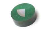 |
ALUMINUM AND ITS ALLOYS |
| Hot process | Phenolic Allylic |
| Cold process | KM-U 2S IP |
Table 3: Choosing the right mounting resin type
When the hard anodizing layer is to be observed, the sample should be mounted using a low-shrinkage resin so as to be able to observe the anodizing layer as well as possible.

POLISHING
PRESI offers a wide range of manual and automatic polishing machines, with a wide choice of accessories, to cover all needs, from pre-polishing to super-finishing and polishing of single or series samples.
The MECATECH range of automatic polishers allows both manual and automatic polishing. With its advanced technologies, motor power from 750-1500W, all the PRESI experience is concentrated in this very complete range. Whatever the sample number or size, MECATECH guarantees optimal polishing.
CONSUMABLES AND POLISHING RANGES
All the first steps of each range are called «levelling» and consist of removing material quickly to level the surface of the sample (and resin). Those given below are standard and can therefore be modified as required.
Applied pressures vary according to sample size, but in general the following applies: 1daN per 10mm mounting diameter for the pre-polishing steps (ex: Ø40mm = 4 daN) then reduce force by 0.5daN at each polishing step with an abrasive suspension.
The following is a general polishing range for aluminum and its alloys:
RANGE N°1
| N° | Support | Suspension / Lubricant | Platen Speed (RPM) | Head Speed (RPM) | Rotation direction platen / head |
Time |
| 1 | P320 | Water / Ø | 300 | 150 | 1’ | |
| 2 | TOP | 9μm LDM / Reflex Lub | 150 | 135 | 4’ | |
| 3 | RAM | 3μm LDM / Reflex Lub | 150 | 135 | 3’ | |
| 4 | NT | 1μm LDM / Reflex Lub | 150 | 135 | 1’ | |
| 5 | SUPRA | SPM / Water | 150 | 100 | 1’ |
For pre-polishing, the head and plate rotation direction should not be reversed, as this can detrimentally affect flatness. However, reversing rotation direction can help if a large amount of material has to be removed.
Diamond polishing can be performed using a monocrystalline diamond suspension. But generally, a polycrystalline diamond solution also works (be careful of possible abrasive grains that can get stuck in the aluminum). This can be useful in the case of consumable rationalisation if aluminum is not the only material to be polished.
If abrasive grains become embedded in the material, it should be polished with the monocrystalline diamond suspension.
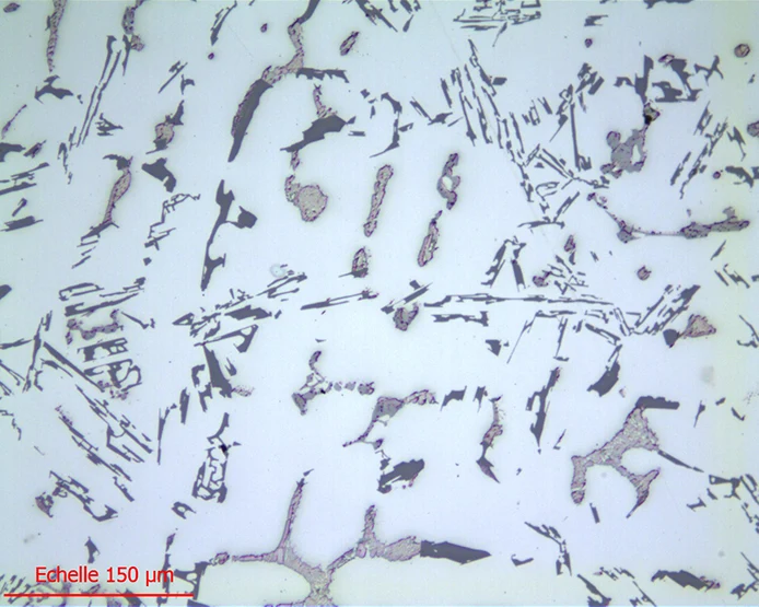
Fig. 13: SPM lensx20 finish
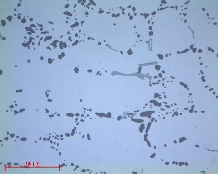
Fig. 14: SPM lensx50 finish
During this step, the rotation of the head is reversed in relation to the platen in order to keep the suspension on the polishing cloth as much as possible.
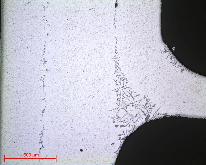
Fig. 15: Alu braze lensx5
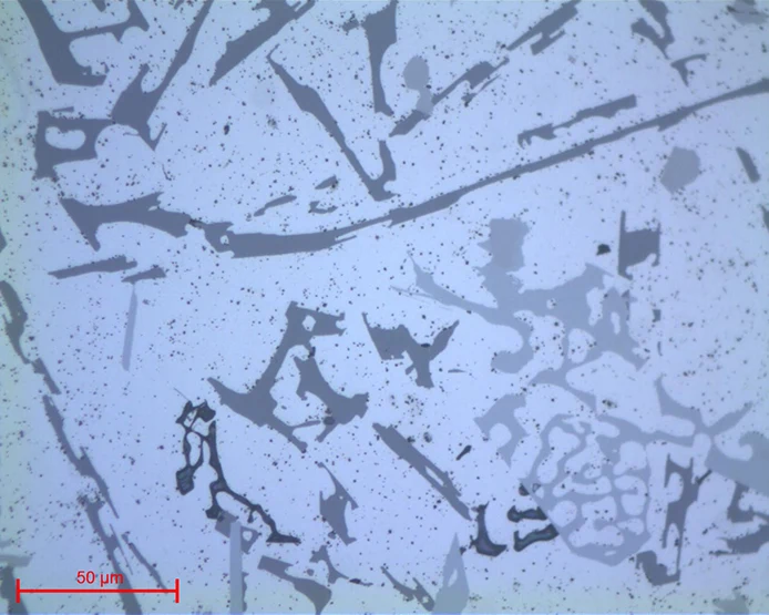
Fig. 16: Alu braze lensx50
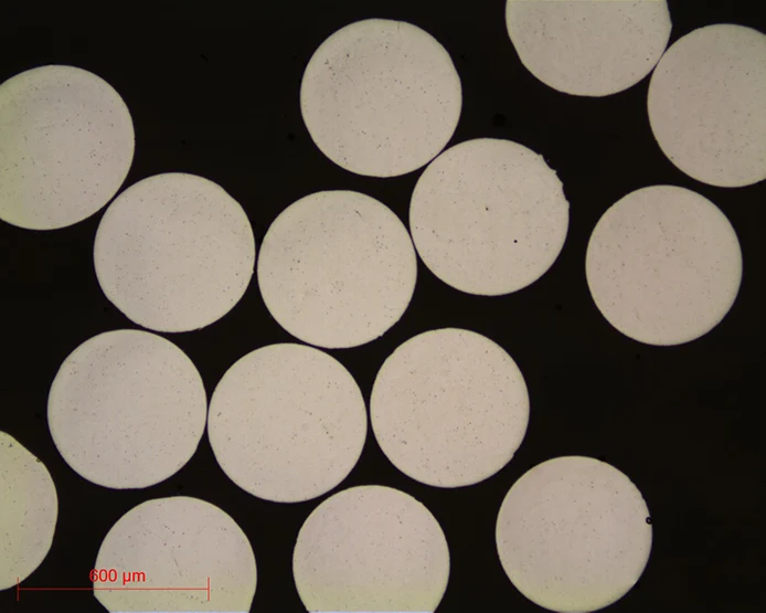
Fig. 17: Aluminum wire lensx5
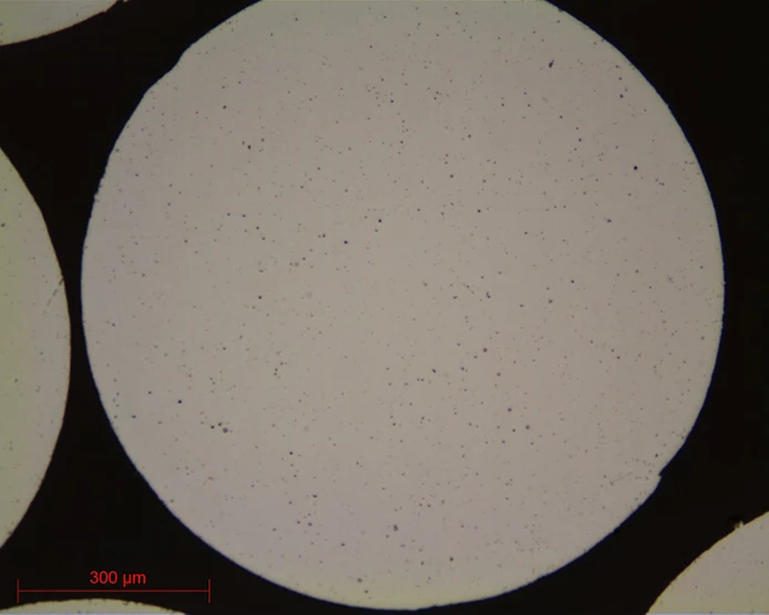
Fig. 18: Aluminum wire lensx10
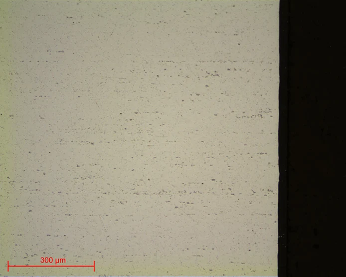
Fig. 19: Anodised aluminum lensx10
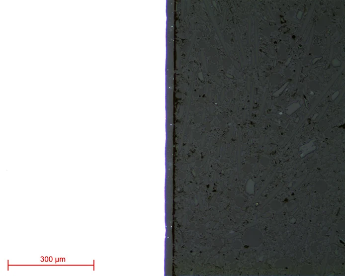
Fig. 20: Anodization lensx10
A second polishing range can be used for polishing aluminum and its alloys:
RANGE N°2
| N° | Support | Suspension / Lubricant | Platen Speed (RPM) | Head Speed (RPM) | Rotation direction platen / head |
Time |
| 1 | P320 | Water / Ø | 300 | 150 | 1’ | |
| 2 | MED-R | 9μm Diamond MED R / Ø | 150 | 135 | 4’ | |
| 3 | RAM | 3μm LDP / Reflex Lub | 150 | 135 | 3’ | |
| 4 | NT | 1μm LDP / Reflex Lub | 150 | 135 | 1’ | |
| 5 | SUPRA | SPM / Water | 150 | 100 | 1’ |
A diamond suspension specially designed for MED-R is used on this support. This suspension combines diamond and lubricant.
For weld inspections, a third Range corresponds specifically to this type of inspection.
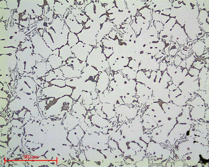
Fig. 21: SPM finish – Range MED-R lensx10
RANGE N°3
| N° | Support | Suspension / Lubricant | Platen Speed (RPM) | Head Speed (RPM) | Rotation direction platen / head |
Time |
| 1 | P320 | Water / Ø | 300 | 150 | 1’ | |
| 2 | TOP | 9μm Gel 2+ poly / Ø | 150 | 135 | 4’ | |
| 3 | ADR II | 3μm Gel 2+ poly / Ø | 150 | 135 | 3’ |
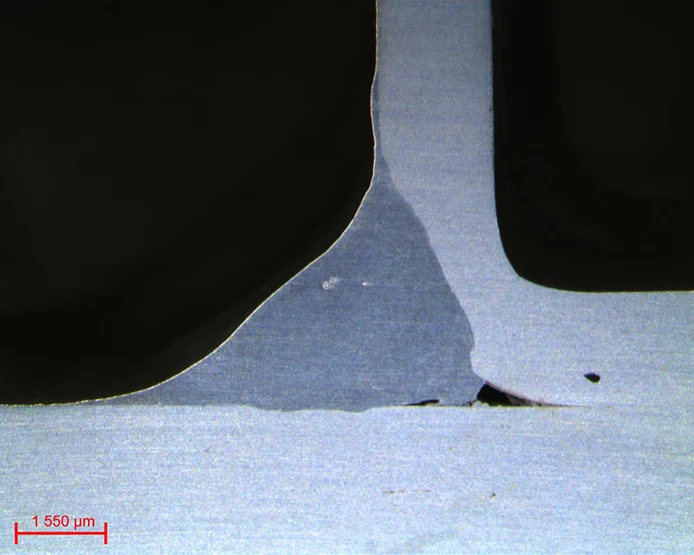
Fig. 22: Aluminum weld
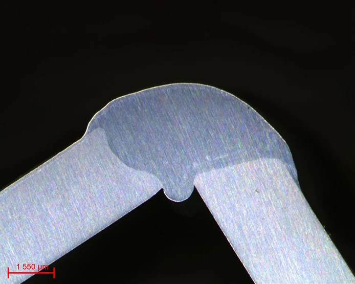
Fig. 23: Aluminum weld

MICROSTRUCTURE
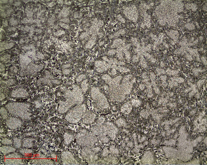
Fig. 24: Structure lensx10
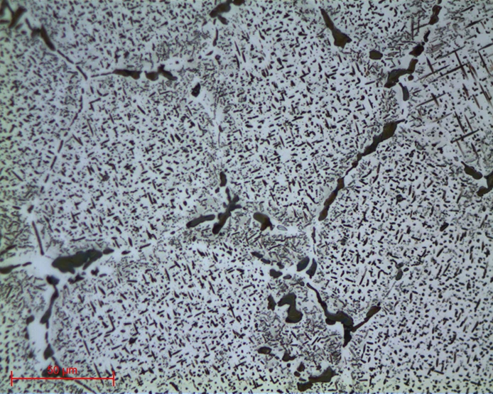
Fig. 25: Structure lensx50
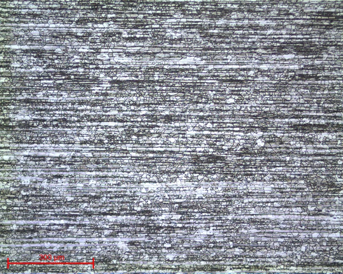
Fig. 26: Aluminum 2024 CS lensx10
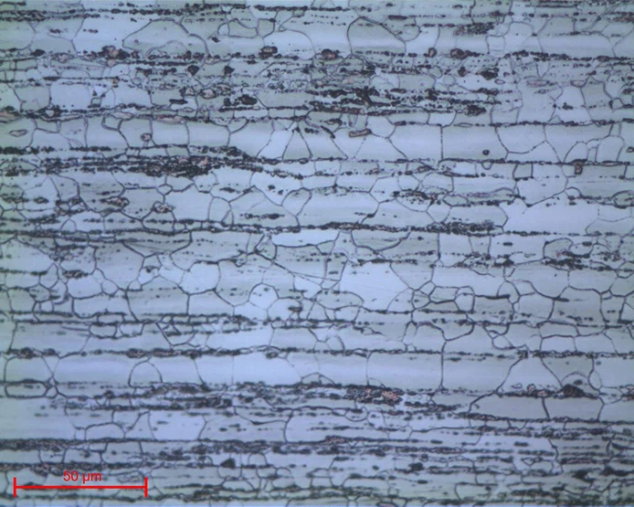
Fig. 27: Aluminum 2024 CS lensx50
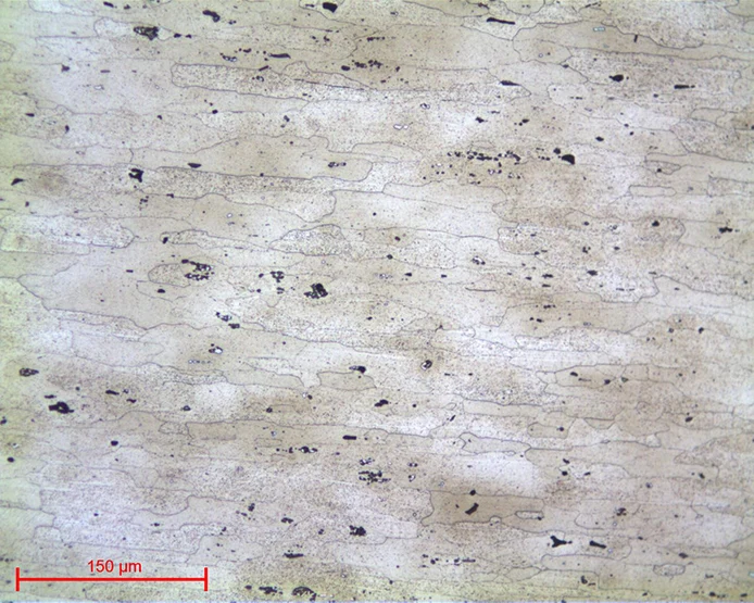
Fig. 28: Structure Aluminum lensx20
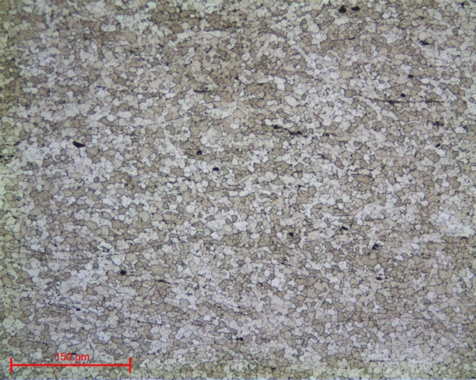
Fig. 29: Structure Aluminum lensx20
DOWNLOAD THE LAB'NOTE
Simply fill out the form below:
Discover our other Lab’Note:
- 3D printing quality control
- Hardened heat treatment control
- Medical device quality control
- Steel quality control
- Stainless steel quality control
- Cast iron quality control
- Copper alloy quality control
- Aluminum quality control
- Nickel quality control
- Titanium quality control
- Ceramic materials quality control
- Electronics quality control
- Precious metal quality control