HARDENED HEAT TREATMENT CONTROL


INTRODUCTION
Heat treatment is a process by which the physical and sometimes chemical properties of steels can be modified. Heat treatment operations take place in several stages with a rise in temperature, maintaining it for a certain time and then slow or rapid cooling.
This can transform the structure of the steel in the mass or superficially.
Additive elements in steels can influence the achievement of the desired structure after heat
treatment.
BENEFITS OF HEAT TREATMENT
With the help of heat treatments, it is therefore possible to increase the hardness of a steel superficially or totally (in the mass) in order to improve resistance to wear or shocks.
It is possible to restore a more homogeneous structure to steels that have undergone grain enlargement, for example.
Heat treatments make it possible to increase the breaking strength, elastic limit, ductility and reduce the brittleness of a steel by removing internal stresses.
=> The aim is therefore to change its physical properties according to the final objective of the steel’s use.
THE MAIN HEAT TREATMENTS
Quenching and tempering
site. The aim is to use the Iron-Carbon diagram (figure 1) to place it in the austenitic range. This diagram is used to deter- mine the temperature of a treatment to make phase transformations. This heating operation is followed by rapid cooling with water, oil or gas. The CCT diagram (continuous cooling trans- formation), determines the cooling conditions that will transform austenite into
Martensite. This type of diagram is specific to each steel grade.
Fig. 1: Fe-C diagram

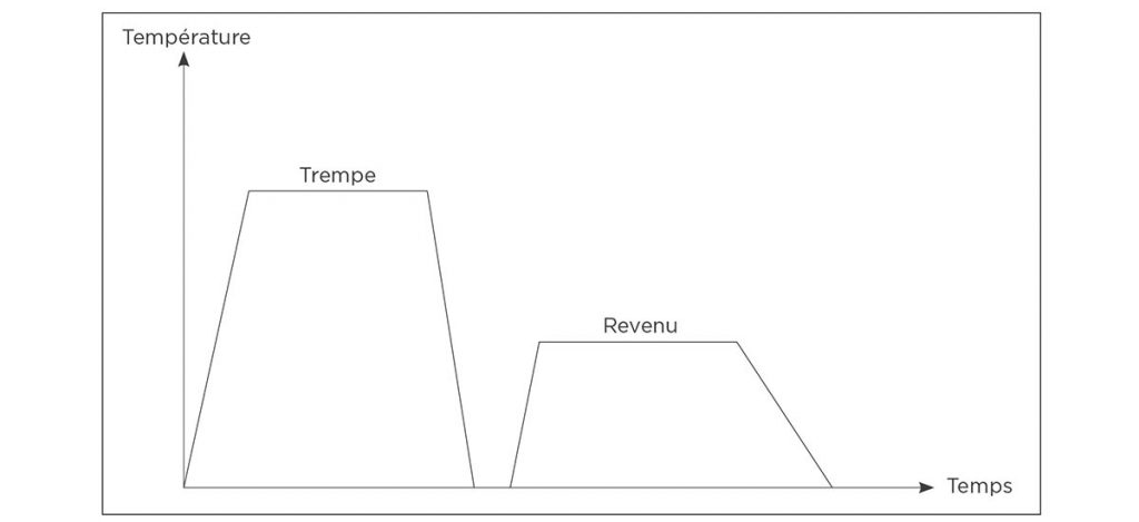
Fig. 2: Quenching and tempering curve
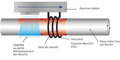
Induction hardening
Fig. 3: Static quenching
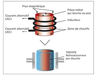
Fig. 4 Flow quenching
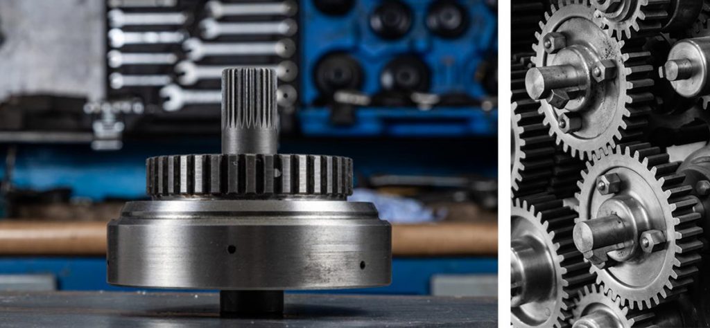
Applications : arbre, engrenages, axe, broche….
Carburizing
The carbon-rich atmosphere (from CH4, propane or butane type gas) enriches the surface layer.
This thermochemical treatment is followed by rapid cooling, which hardens the enriched layer.
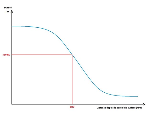
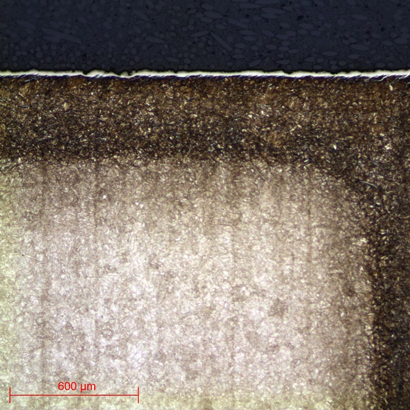
The Case Hardness Depth (CHD) is determined by the vertical distance from the surface to the layer at a hardness limit of 550 HV. Case Hardness Depth generally varies between 0.5mm and 3mm.
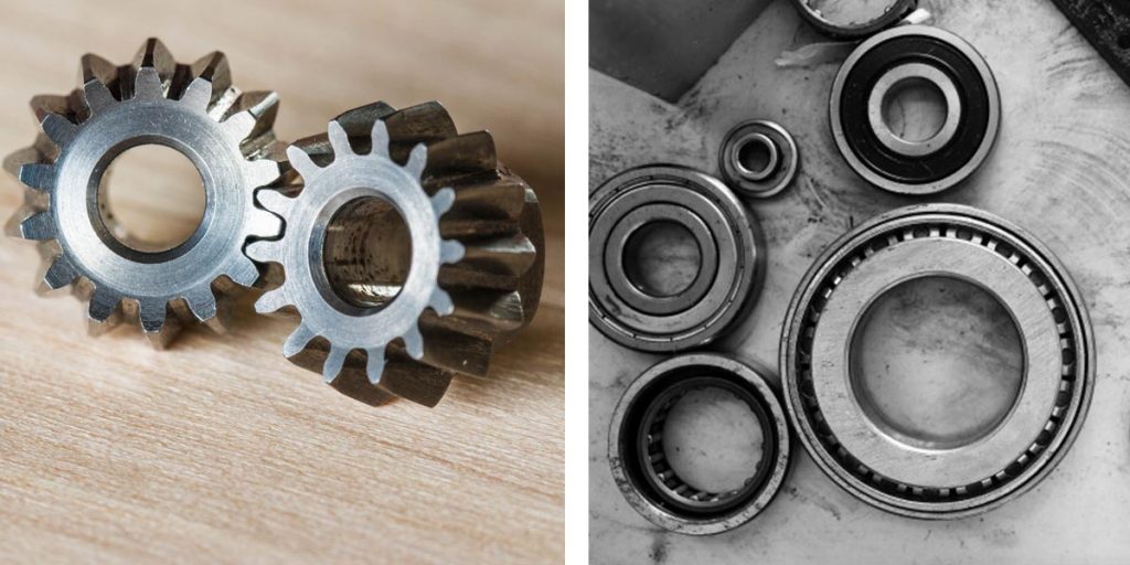
Applications are mainly mechanical parts such as gears, transmission shafts, etc.
Carbonitriding
Nitriding
It is therefore the diffusion of nitrogen on the surface of an alloy steel (which contains chro- mium, aluminum, tungsten, etc.). It is general- ly performed at between 500 and 550°C.
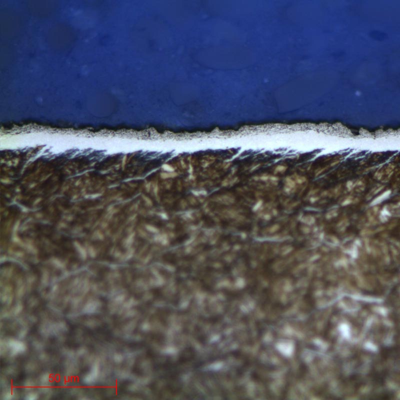
Nitriding consists of two layers:
• The combination layer (“white layer”): a nitride layer on the surface which consists of the chemical compounds present in the treatment atmosphere and the base metal.
The thickness can vary from 5 to 30μm. This layer has a very high wear resistance. Its hard- ness generally ranges from 950 to 1100 HV.
The nitriding depth (NHT) is determined by the hardness curve according to DIN 50190-3 or ISO 18203.
After making three core hardness indentations, the nitriding depth corresponds to this value HV core + 50 HV.
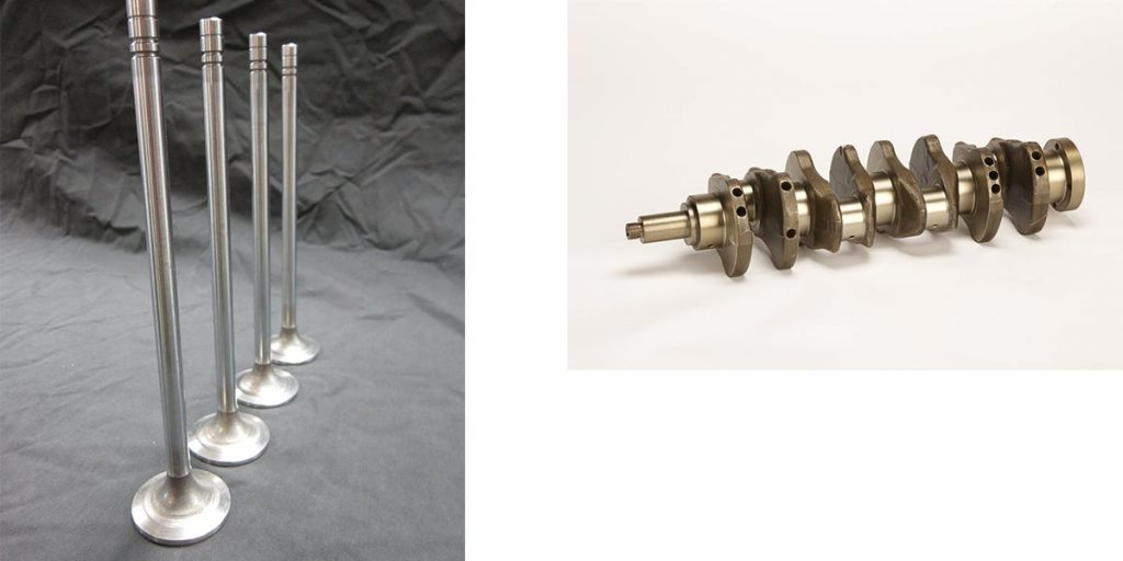
Applications : axe de piston, vilebrequin, soupape…
METALLOGRAPHIC PREPARATION
• The removal of the product to be examined (if necessary), called “CUTTING”.
• Standardisation of the geometry of the sample taken (if necessary), called “MOUNTING”.
• Improvement of the surface condition of this sample, called “POLISHING”.
• Characterisation of the sample: revealing the microstructure of the sample by an etching reagent (if necessary) called “METALLOGRAPHIC ETCHING” and microscopic observation (optical or electronic).
=> Each of these steps must be carried out rigorously, otherwise the following steps will not be possible.

CUTTING
In other words, it is essential to avoid heating or any deformation of the metal that could lead to degradation of the material. Cutting is fundamental step which conditions the further preparation and inspection of parts.
PRESI’s wide range of medium and large capacity cutting and micro-cutting machines can be adapted to any need with regard to cutting precision, sizing or quantity of products to be cut:

• The Mecatome ST310 is perfectly adapted to the field of heat treatment. It is a powerful and robust manual machine. The oscillating arm allows fast cuts without effort or burning.
=> The main advantage of the Mecatome ST310 is its oscillating movement. This allows the grin-
ding wheel to never have the same point of contact with the workpiece, so there are no burns (if the chosen consumable is suitable for the material) and the cutting time is faster than with only a pendulum movement.
• The EVO 400 is a high-capacity cutting machine. It is robust, powerful and very spacious. It is
suitable for workshops and offers three cutting modes: assisted, automatic and programmable (for
repeatability of cuts). Its touch screen facilitates the man-machine interface.
This machine can also offers the pulse cutting feature. It is perfectly adapted for parts with internal constraints. Pulse cutting consists of alternating feed and pause during cutting. This gives the stresses inside the material time to gradually release.
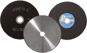
Each of the cutting machines in the range has its own customised consumables and accessories. The clamping system and choice of consumables are key factors in a successful metallographic cut.
=> Clamping, i.e. holding the workpiece, is essential. If the workpiece is not held properly, the cut can be detrimental to the cut-off wheel, the workpiece and the machine.

")
")
CONSUMABLES
 |
Aciers traités
superficiels |
Aciers traités
à coeur |
| Micro-tronçonnage | S Ø180 mm
UTW AO |
S Ø180 mm
CBN |
| Tronçonnage de moyenne capacité | AO | S
CBN |
| Tronçonnage de grande capacité | AO | S |
Table 1: Choosing the right cut-off wheel type
MOUNTING
=> Achieving good-quality mounting is essential to protect fragile materials and also to achieve good preparation results for polishing and future analysis.
Before mounting, the sample should be deburred with coarse abrasive paper, for example, to remove any cutting burrs. Cleaning with ethanol (in an ultrasonic tank for even greater efficiency) is also possible. This allows the resin to adhere as well as possible to the sample and thus limits shrinkage (space between the resin and the sample).
If shrinkage persists, it can lead to problems during polishing. Abrasive grains may become lodged in this space and then be released at a later stage, thus creating a risk of pollution for the sample and the polishing surface. In this case, cleaning with an ultrasonic cleaner between each step is recommended.
There are two mounting options:
• HOT MOUNTING is to be preferred for edge inspection purposes or if the metallographic preparation is carried out in preparation for hardness testing. This option requires a hot-mounting machine.
• Fully automatic hot-mounting press.
• Easy to use: memorisation, adjustment of processes and speed of execution make it a high-precision machine,
• The hot-mounting machine has 6 different mould diameters from 25.4-50mm.
POINT +
• If the parts to be examined are fragile/sensitive to pressure
• If they have a complex geometry such as a honeycomb structure.
• If a large number of parts are to be mounted in series.
Fig 13: Pressurized mounting device
The cold process can be used with:
+ POINT
+ POINT
CONSUMABLES
Cold mounting is also more flexible, hence the existence of rectangular moulds for more specific needs.
In order to reduce costs, it is possible to introduce the epoxy resin in the sole (i.e. in contact with the surface of the sample to be observed) and fill the rest with a less qualitative, and therefore less expensive, phenolic resin. If cold mounting has to be performed on treated steels, it is preferable to opt for KM-B or KM-U acrylic resin, both of which have hardnesses close to those of hot resins.
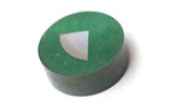
Table 2: Choosing the right mounting resin type

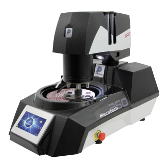
POLISHING
PRESI offers a wide range of manual and automatic polishing machines, with a wide choice of accessories, to cover all needs, from pre polishing to super-finishing and polishing of single or series samples.
For hardness testing, polishing with an automatic polishing machine from the Mecatech range seems to be the most suitable.
CONSUMABLES AND POLISHING RANGE
Applied pressures vary according to sample size, but in general the following applies: 1daN per 10mm mounting diameter for the pre-polishing steps (ex: Ø40mm = 4 daN) then reduce force by 0.5daN at each polishing step with an abrasive suspension.
This range is suggested for superficially and core-treated steels:
Grinding is performed using I-Max R discs. These resin-bonded diamond discs can replace several hundred abrasive papers. They provide good flatness for polishing hard ferrous materials.
When grinding, it is not necessary to reverse the rotation direction of the head and platen as this can detrimentally affect flatness. However, reversing the directions of rotation can help if a large amount of material has to be removed.
A 3-step range is sufficient for hardness testing. The scratch pattern obtained with the 3μm suspension is fine enough to allow the hardness indentations to be read. The RAM cloth can also be replaced by ADRII cloth.
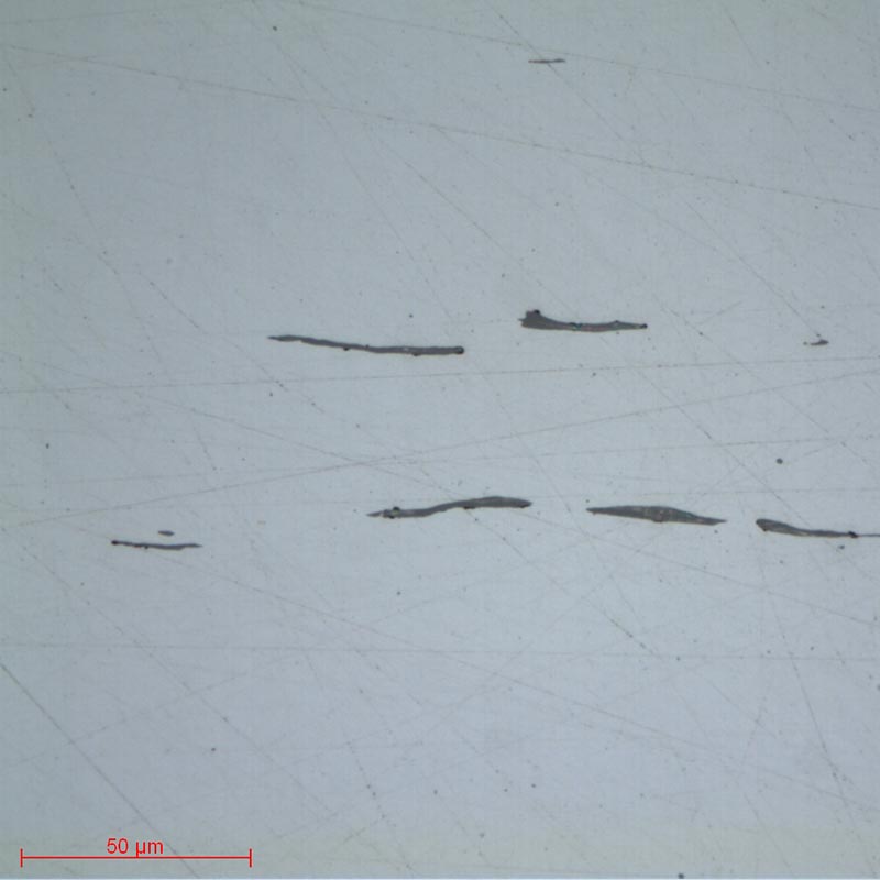
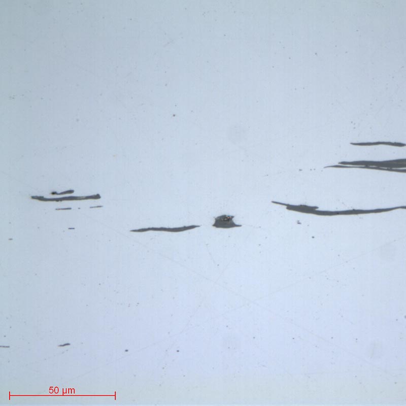
Finally, a superfinish with PRESI n°3 alumina can be used to make an inclusionary check for example.
| N° | Support | Suspension /
Lubricant |
Speed (RPM) |
Head Speed (RPM) |
Rotation direction platen / head |
Time |
| 1 | I-Max R
54μm |
Ø / Water | 300 | 150 | 3’ | |
| 2 | MED-R | 9μm super
abrasive / Ø |
150 | 135 | 4’ | |
| 3 | RAM | 3μm LDP /
Reflex Lub |
150 | 135 | 3’ | |
| 4 | NT | 1μm LDP /
Reflex Lub |
150 | 135 | 1’ | |
| 5 | NT | Al2O3 n°3 /
Water |
150 | 100 | 1’ |
For diamond polishing, steps 3 and 4 are carried out using LDP concentrated polycrystalline suspensions. Polycrystalline diamond has sharp angles which are suitable for polishing medium-hard to hard materials.
If the materials to be polished are sensitive to corrosion, LDP diamond suspensions can be replaced by alcohol-based, anhydrous polycrystalline ADS diamond suspensions.
Sometimes it is necessary to adapt the range according to the treatment, especially in the case of
nitrided steels.
| N° | Support | Suspension /
Lubrifiant |
Platen Speed (RPM) | Head Speed (RPM) | Rotation direction platen/head | Time |
| 1 | Sic P320 | Ø / Water | 300 | 150 | 1’ | |
| 2 | TOP | 9μm LDP /
Reflex Lub |
150 | 135 | 4’ | |
| 3 | RAM | 3μm LDP /
Reflex Lub |
150 | 135 | 3’ | |
| 4 | NT | 1μm LDP /
Reflex Lub |
150 | 135 | 1’ | |
| 5 | NT | Al2O3 n°3 /
Water |
150 | 100 | 1’ |
For nitrided steels, polishing with I-Max R or MED-R is too aggressive and could damage the combination layer. It is therefore preferable to replace the I-Max R with a P320 abrasive paper.
The following steps are carried out conventionally using polishing cloths and LDP diamond suspen- sions and the associated lubricant Reflex LUB. Finally, superfinishing is optional using alumina on an NT flocked cloth.
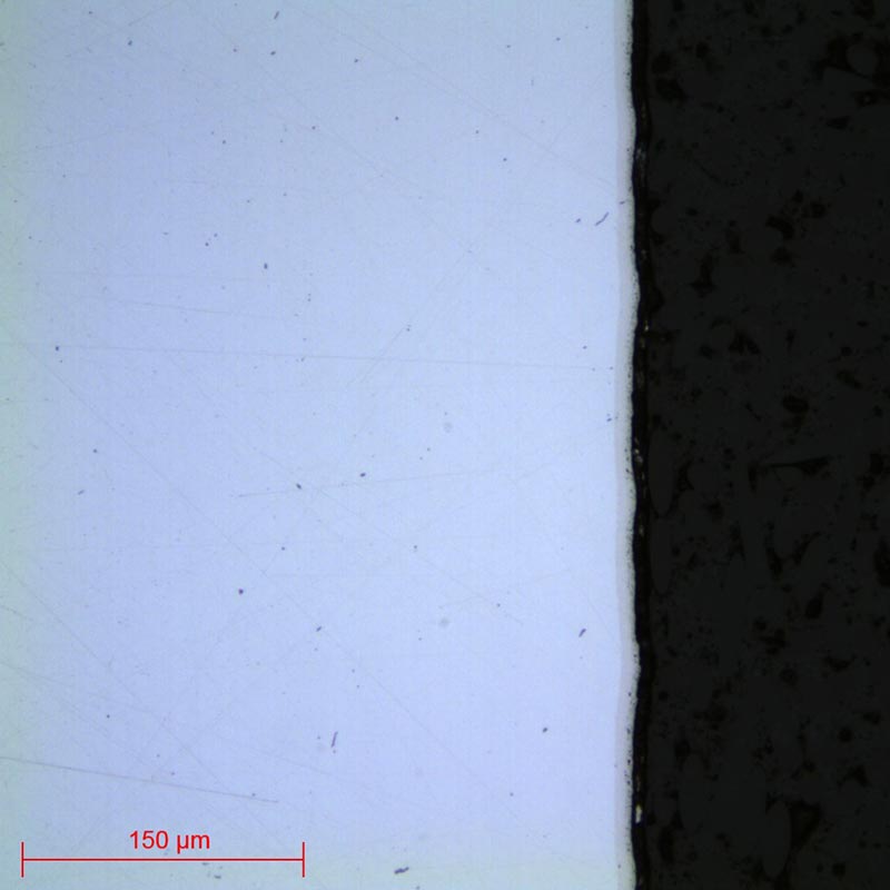
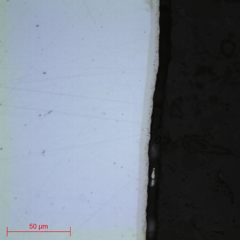
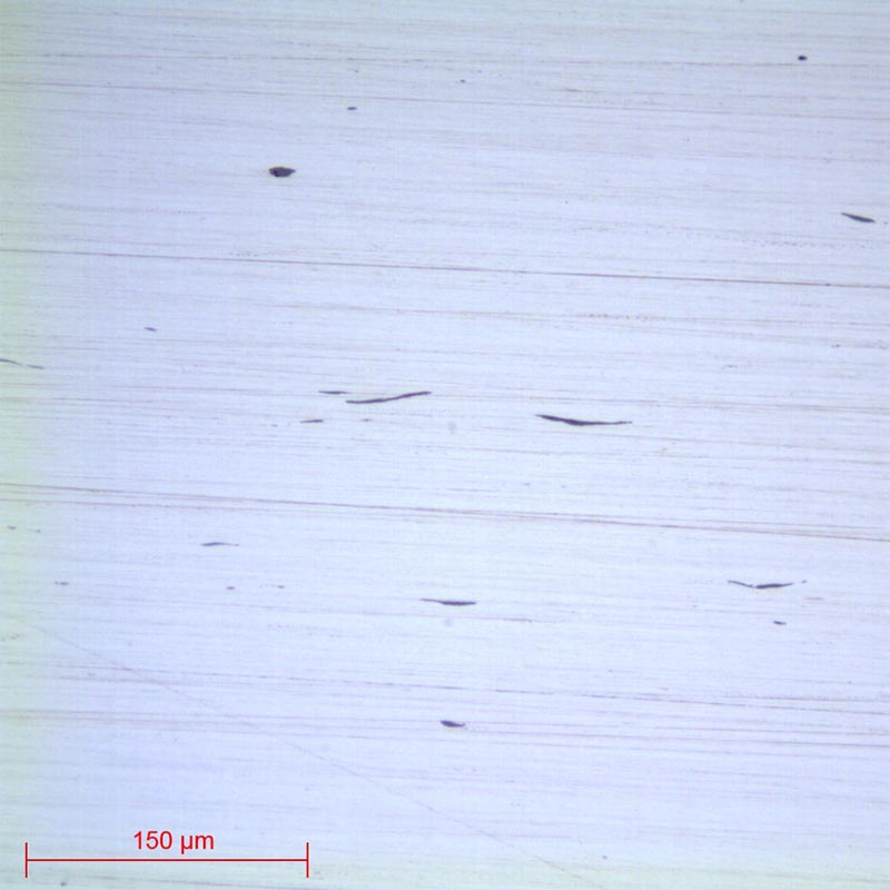
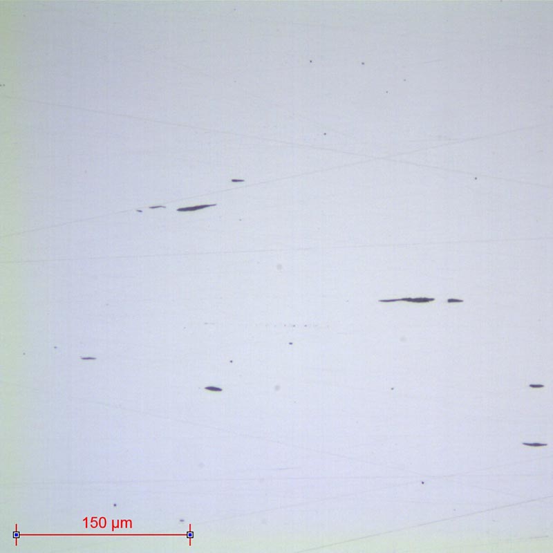
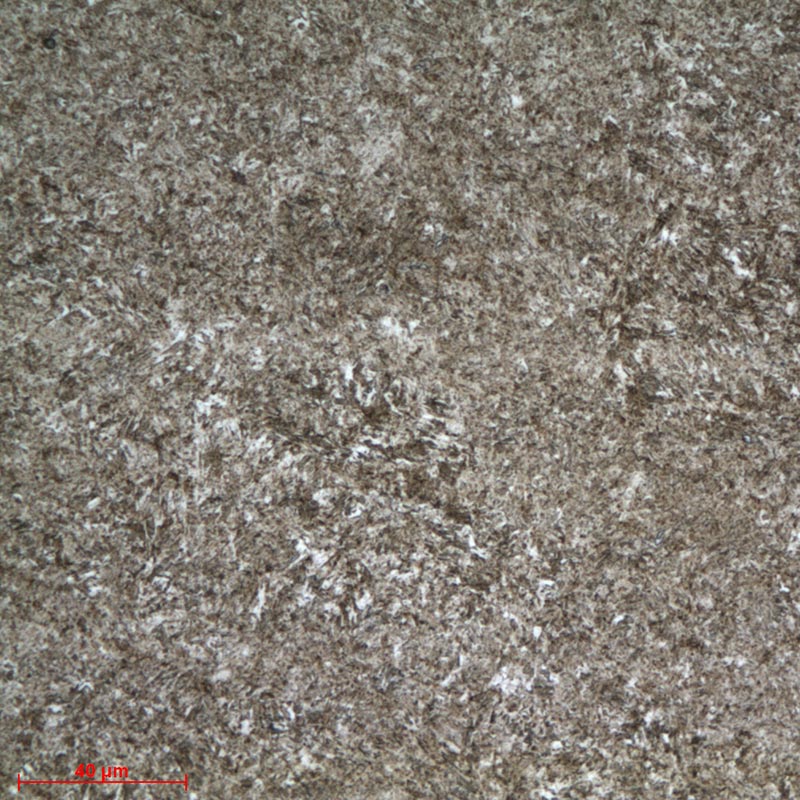
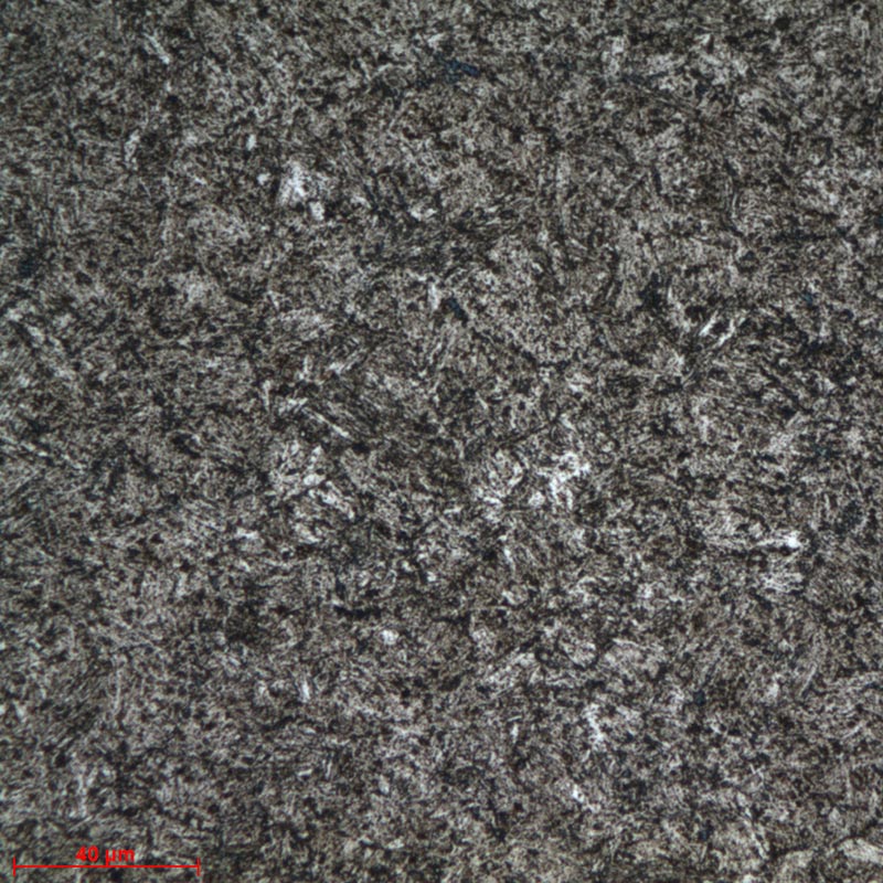
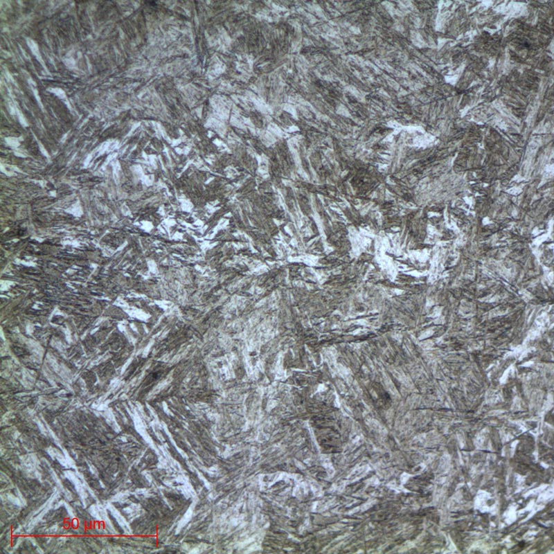
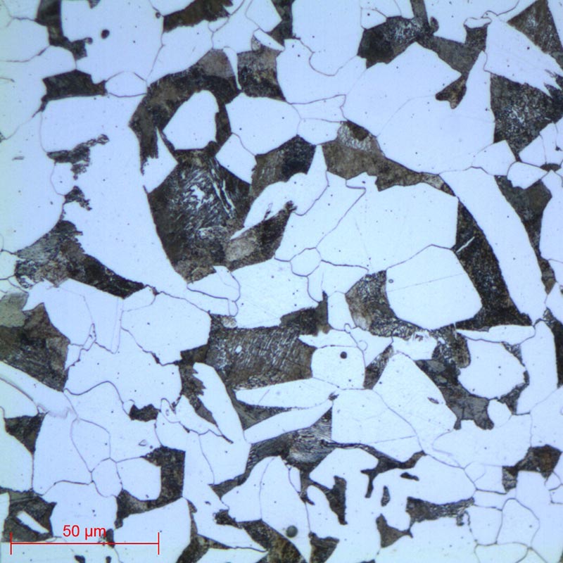
MICROSTRUCTURE

HARDNESS PATTERNS
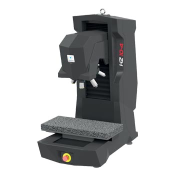
To carry out these hardness tests, the HZ 10-4 hardness tester should be used, with the PRESI Touch Pattern software.
A macroscopic camera is available as an option and provides an overall view of the part (facili- tates the positioning of patterns).
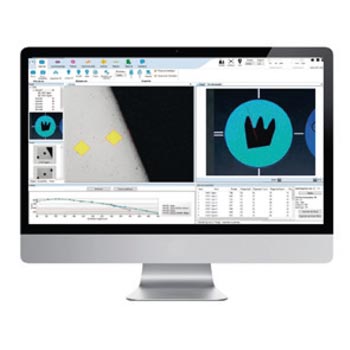
Navigation is intuitive and all functions are directly accessible. Data and results are displayed at all times.
Patterns can be regular or irregular and it is possible to make isolated points. A preview of the indents helps to position the pattern before testing.
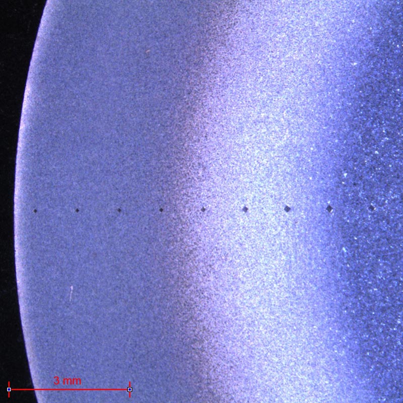
Fig. 28: HZ 10-4 hardness tester
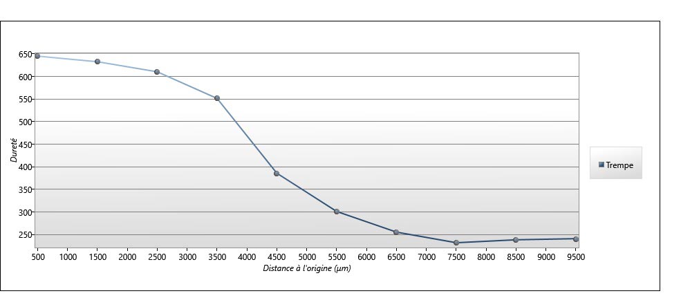
Fig. 31: Graph of induction-treated steel
DOWNLOAD THE LAB'NOTE
Simply fill out the form below:
Discover our other Lab’Note:
- 3D printing quality control
- Hardened heat treatment control
- Medical device quality control
- Steel quality control
- Stainless steel quality control
- Cast iron quality control
- Copper alloy quality control
- Aluminum quality control
- Nickel quality control
- Titanium quality control
- Ceramic materials quality control
- Electronics quality control
- Precious metal quality control