CERAMIC MATERIALS
QUALITY CONTROL


INTRODUCTION
They have high melting points, very high hardness and no ductility. Common manufacturing processes (machining, casting, plastic deformation, etc.) are therefore either unsuitable or only marginally so. Manufacture involves manipulating a powder before the product consolidation operation.
PRODUCTION PROCESS
which consist of dispersing ceramic powders in a solvent (water, alcohol, etc.) in order to obtain a suspension with the desired properties (solvents are then eliminated during subsequent thermal cycles). This suspension obtained makes it possible to carry out casting operations in moulds or tape and deposits by dipping.
Example of tape casting: the suspension is laminated and then dried by infrared radiation before being laser-cut and assembled into multiple layers.
which involve mixing technical ceramic powders with organic bonds in order to obtain a fluid (bonds are removed in subsequent thermal cycles). It is then shaped by injection or extrusion.
Example of injection: the “ceramic fluid” is fed into the hopper, then heated, compressed and injec- ted into the mould before being cooled and removed from the mould.
to agglomerate powder particles for mould filling, giving them sufficient plasticity for deformation during pressing.
Example of single-axis pressing: the mould is filled with the ceramic powders which are then pressed and subsequently removed from the mould.
Technical ceramics have a variety of physical properties that offer suitable solutions where metallic materials and polymers may be ineffective.
Among these properties, the most important are the following:
• Mechanical properties: their extreme hardness offers very good resistance to wear, abrasion and compression.
• Thermal properties: resistant to very high temperatures (up to 2,000°C), ceramics are the reference in refractory materials.
• Electrical properties: some ceramics are excellent electrical insulators and others, on the contrary, are (super)conductors.
• Chemical properties: some possess chemical inertness, biocompatibility and vacuum tightness.
• Optical properties: some transparent ceramics have exceptional optical properties (visible, IR or UV ranges).
=> All these properties make technical ceramics remarkable materials with numerous industrial applications:
The electronics field accounts for 70-75% of global turnover for technical ceramics. Their various compositions and properties of use mean electronic ceramics can be used in a variety of applications: electrical insulation (Al2O3, SiO2, MgO, etc.), semiconductors (SiC, Cu2O, TiO2, etc.), electrical conductors (ReO2, MoSi2 LaB6, etc.) and magnetic ceramics (Fe3O4, NiFe2O4, etc.).
The medical field also uses ceramics, commonly known as “bioceramics”. They are used in medical instruments and systems, reconstructive surgery (prostheses, implants, bone substitutes, etc.) and in the dental field (implants, bridges, etc.). Alumina (Al2O3) and zirconium dioxide (ZrO2) are the most commonly-used ceramics due to their density, purity, tribological qualities and mechanical resistance.
Technical ceramics are commonly used as filters or membranes in the energy and environment fields. Particle filters or catalytic converters (some with honeycomb structure) are made using ceramics and allow the filtering and/or degradation of gas pollutants (SiC often used for its thermal conductivity but also Al2O3, CeO2, ZrO2 on which noble metals are deposited in the particular case of catalytic converters). Ceramics are also used as fuels in the nuclear field (UO2, PuO2, etc.).
The use of ceramic components in the telecommunications field now holds sway, in particular due to their resistance to their environment and the stresses to which they are subjected (humidity, vibrations, temperature variations, etc.).
In the aerospace field too, technical ceramics have a multitude of applications (turbine blades, telescope mirrors, sensors, combustion chambers, engines, etc.).
In order to compensate for their fragility, ceramics can be used as components of composite mate- rials. Ceramics generally make up the matrix containing a set of fibres (glass, carbon, silicon carbide, etc.) called “strengthening”. These composites are called “ceramic matrix composites” (CMC).

METALLOGRAPHIC PREPARATION
Obtaining an inspection surface requires a succession of operations, each as important as the next, regardless of the material. These steps are in the following order:
• Standardisation of the geometry of the sample taken (if necessary), called “MOUNTING”.
• Improvement of the surface condition of this sample, called “POLISHING”.
• Characterisation of the sample: microscopic observation (optical or electronic).

CUTTING

=> Clamping, i.e. holding the workpiece, is essential. If the workpiece is not held properly, the cut can be detrimental to the cut-off wheel, the workpiece and the machine.
CONSUMABLES
 |
Ceramics |
| Micro-cutting | LM / LM+ / LR |
| Medium-capacity cutting | LM / LM+ / LR |
| High-capacity cutting | LM / LM+ / LR |
Table1: Choosing the right cut-off wheel type

MOUNTING
Achieving good-quality mounting is essential to protect fragile materials and also to achieve good preparation results for polishing and future analysis.
Before mounting, the specimen should be deburred with coarse abrasive paper, for example, to remove any cutting burrs. Cleaning with ethanol (in an ultrasonic tank for even greater efficiency) is also possible. This allows the resin to adhere as well as possible to the sample and thus limits shrinkage (space between the resin and the sample).
If shrinkage persists, it can lead to problems during polishing. Abrasive grains may become lodged in this space and then be released at a later stage, thus creating a risk of pollution for the sample and the polishing surface. In this case, cleaning with an ultrasonic cleaner between each step is recommended.
As ceramic materials are fragile, the hot mounting process is not possible because the pressures exerted are too high and could therefore damage the samples. In such cases, the cold mounting process is to be preferred. Some complex geometries also require cold mounting to allow the resin to impregnate the specimen as well as possible. This type of mounting is also preferred if a large number of parts are to be mounted in series.
COLD MOUNTING
+ POINT
+ POINT
CONSUMABLES
The cold process has different mounting moulds with diameters from 20-50mm. These are divided into several types: optimised moulds called “KM2.0”, rubber, Teflon or polyethylene moulds. Cold mounting is also more flexible, hence the existence of rectangular moulds for more specific needs.
 |
Ceramics |
| Cold process | KM-U KM-B IP – IP FAST 2S* |
Table 2: Choosing the right mounting resin type
* Suitable for very large series

POLISHING
PRESI offers a wide range of manual and automatic polishing machines, with a wide choice of accessories, to cover all needs, from pre-polishing to super-finishing and polishing of single or series samples.
The MECATECH range of automatic polishers allows both manual and automatic polishing. With its advanced technologies, motor power from 750-1500 W, all the PRESI experience is concentrated in this very complete range. Whatever the sample number or size, MECATECH guarantees optimal polishing.
CONSUMABLES AND POLISHING RANGE
All the first steps of each range are called “levelling” and consist of removing material quickly to level the surface of the sample (and resin). Those given below are standard and can therefore be modified as required.
Applied pressures vary according to sample size, but in general the following applies: 1daN per 10mm mounting diameter for the pre-polishing steps (ex: Ø40mm = 4 daN) then reduce force by 0.5daN at each polishing step with an abrasive suspension.
RANGE N°1
| N° | Support | Suspension / lubricant |
Platen Speed (RPM) |
Head Speed (RPM) |
Rotation direction platen / head |
Time |
| 1 | Tissediam 40μm | Ø / Water | 300 | 150 | 2’ | |
| 2 | Tissediam 20μm | Ø / Water | 300 | 150 | 2’ | |
| 3 | TOP | 9μm LDP / Reflex Lub |
150 | 135 | 5’ | |
| 4 | NWF+ | 3μm LDP / Reflex Lub |
150 | 135 | 2’ | |
| 5 | SUPRA | SPM / Water |
150 | 100 | 2’ |
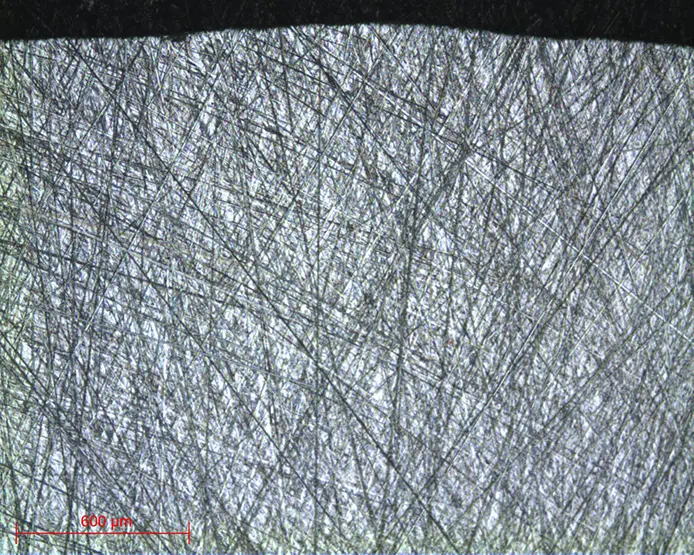
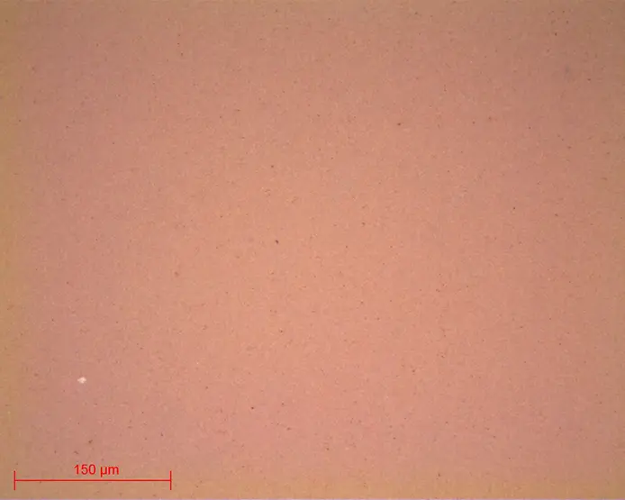
Micrograph 1: zirconium dioxide ZrO2
Surface condition TISSEDIAM 40μm lens x5
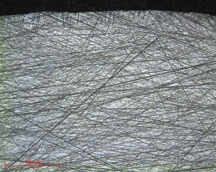
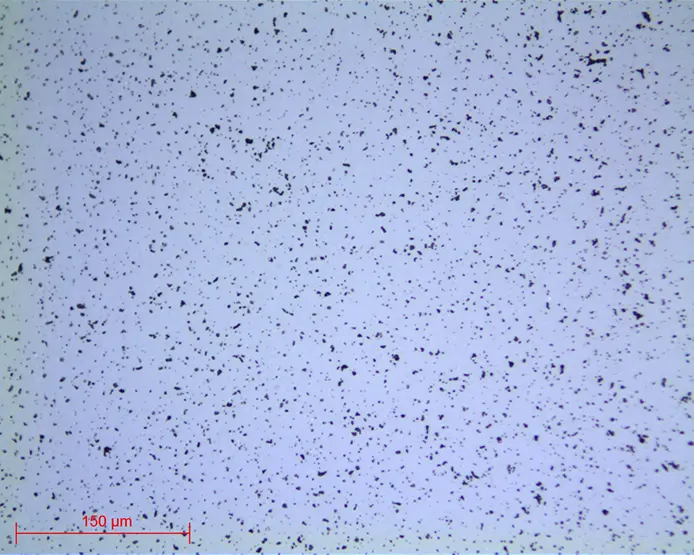
Micrograph 2: zirconium dioxide ZrO2
Surface condition TISSEDIAM 20μm lens x5
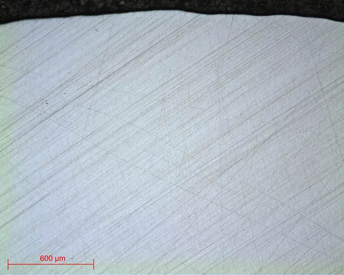
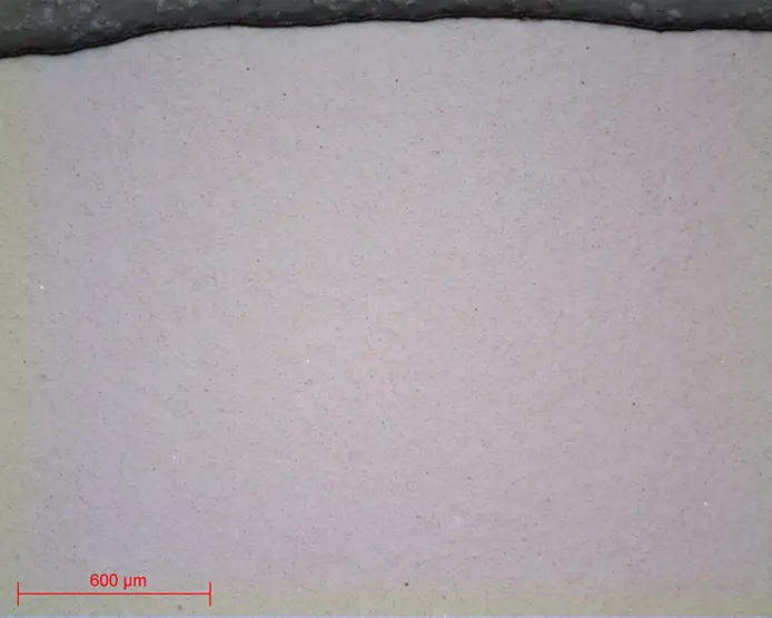
Micrograph 3: zirconium dioxide ZrO2
Surface condition TOP 9μm lens x5
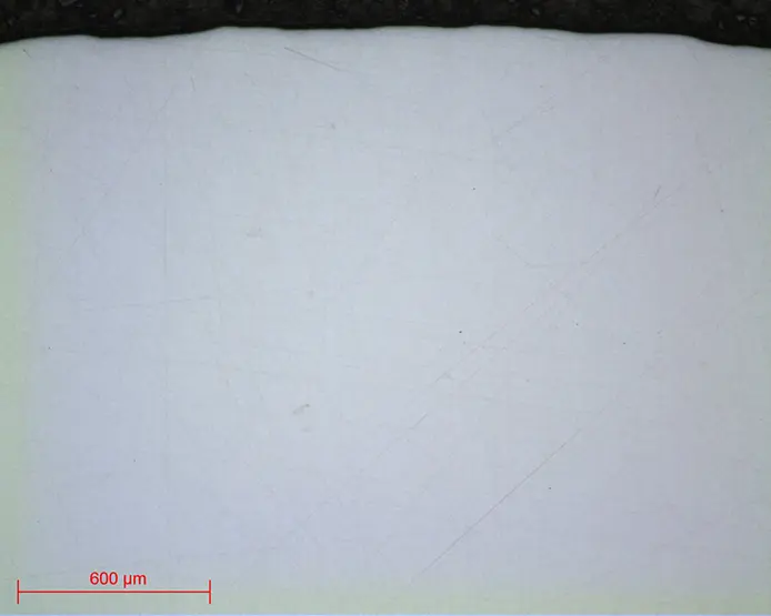
Micrograph 4: zirconium dioxide ZrO2
Surface condition NWF+ 3μm lens x5
Micrograph 5: zirconium dioxide ZrO2
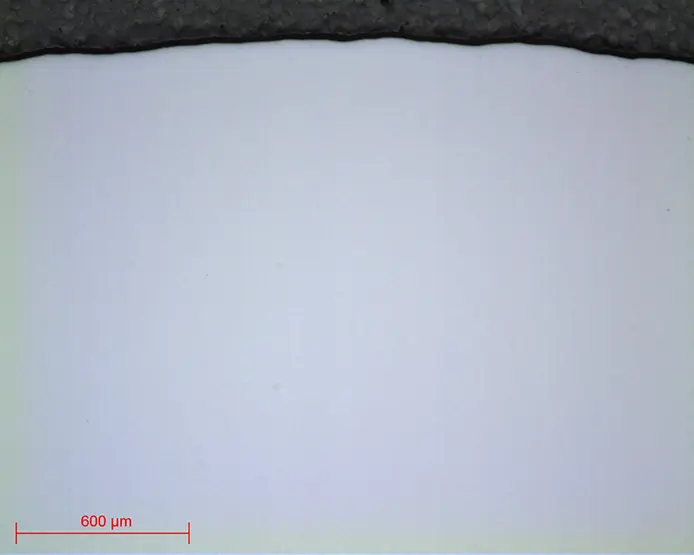
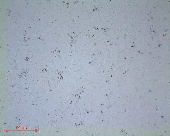
Surface condition SPM lens x5
RANGE N°2
| N° | Support | Suspension / lubricant |
Platen Speed (RPM) |
Head Speed (RPM) |
Rotation direction platen / head |
Time |
| 1 | I-MAX R 54μm | Ø / Water | 300 | 150 | 3’ | |
| 2 | I-MAX R 18μm | Ø / Water | 300 | 150 | 3’ | |
| 3 | TOP | 9μm LDP / Reflex Lub |
150 | 135 | 4’ | |
| 4 | RAM | 3μm LDP / Reflex Lub |
150 | 135 | 3’ | |
| 5 | NV | CeO2 / Water | 150 | 100 | 1’ |
All the polishing ranges listed above are standard and versatile ranges that can be modified according to the subtleties of the samples. (Cf Lab’Notes of the material concerned).
Moreover, they are not necessarily to be carried out in their entirety; observations will define needs (except for titanium samples for which all the steps of the range must be performed).
At the end of this preparation phase, the polished samples can be directly observed without metallographic etching. Otherwise, metallographic etching allows differences in relief and/or colour to be made between the different components and so allows them to be observed. It is mainly used on metals (see Lab’Notes on the material concerned).

MICROSCOPY
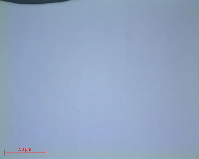
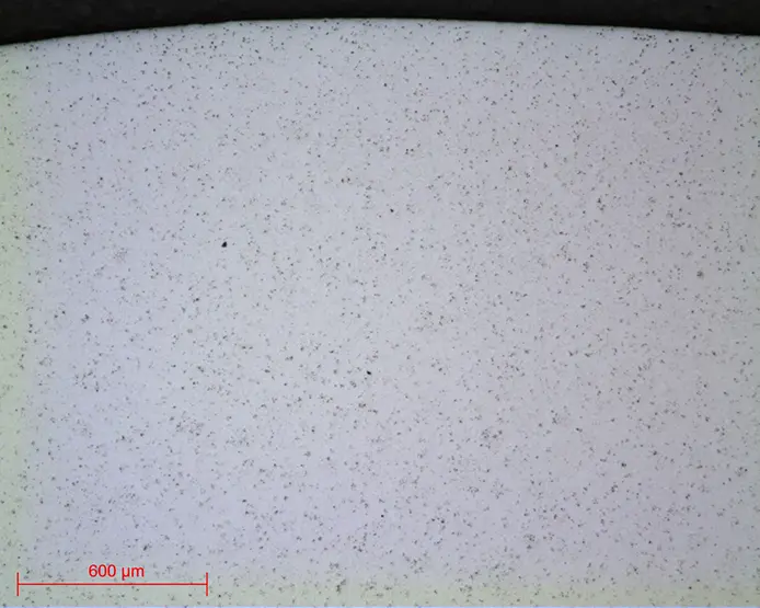
Micrograph 6: Alumina Al2O3
Polished to SPM lens x50
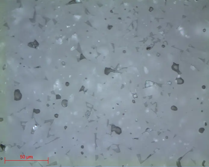
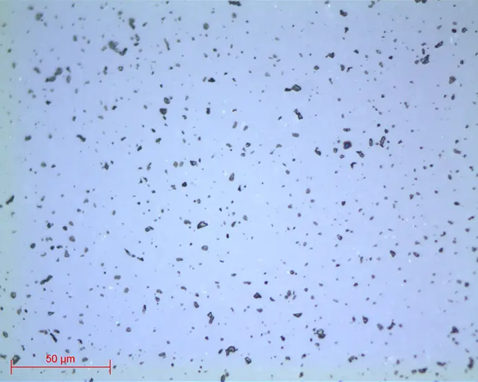
Micrograph 7: Zirconia ZrO2
Polished to SPM lens x5
Micrograph 8: Zirconia hardened alumina ZTA
Polished to SPM lens x5
Micrograph 9: Zirconia hardened alumina ZTA
Polished to SPM lens x20
Micrograph 10: Silicon Carbide SiC
Polished to SPM lens x20
Micrograph 11: Silicon Carbide SiC
Polished to SPM lens x50
Micrograph 12: Tungsten carbide WC
Polished to SPM lens x5
Micrograph 13: Tungsten carbide WC
Polished to SPM lens x50
DOWNLOAD THE LAB'NOTE
Simply fill out the form below:
Discover our other Lab’Note:
- 3D printing quality control
- Hardened heat treatment control
- Medical device quality control
- Steel quality control
- Stainless steel quality control
- Cast iron quality control
- Copper alloy quality control
- Aluminum quality control
- Nickel quality control
- Titanium quality control
- Ceramic materials quality control
- Electronics quality control
- Precious metal quality control