STAINLESS STEEL QUALITY CONTROL


INTRODUCTION
Symbol: Fe
Atomic N°: 26
Density: 7,8
Molar mass: 55,8 g.mol-1
Melting point: 1538 °C
Symbol: C
Atomic N°: 6
Density: 2,1 – 2,3 (graphite)
Molar mass: 12 g.mol-1
Symbol: Cr
Atomic N°: 24
Density: 7,15
Molar mass: 52 g.mol-1
Melting point: 1907 °C


STAINLESS STEEL METALLURGY
- Ferritic stainless steels have very low carbon content (< 0.1%) and therefore have a ferritic structure. Their resistance to corrosion increases according to their chromium content, which can range from 12% to more than 25%. These steels are magnetic, and when stabilised (addition of titanium, niobium and zirconium) they are weldable. However, their structure limits their mechanical properties (strength and hardness inparticular).
Example of grade: X6Cr17 (AISI: 430). - Martensitic stainless steels have sufficient carbon content (> 0.08% and up to 1.2%). They are composed of 12-18% chromium and generally have lower corrosion resistance than other classes of stainless steel due to their martensitic structure. This structure is obtained by heat treatment and these stainless steels behave similarly to conventional treated steels. They are therefore magnetic and are used where high mechanical characteristics are required.
Example of grade: X20Cr13 (AISI: 420). - Austenitic stainless steels are the most commonly used. They have excellent corrosion resistance and high ductility. Their chromium content is 16-20% and they have fairly high nickel content, usually 8-10%. It is this nickel content that gives stainless steel its austenitic structure. Other elements can be added and/or the carbon content reduced in order to improve corrosion resistance. This structure makes these stainless steels non-magnetic. Their mechanical properties are influenced by cold treatment (hot treatment is not possible).
Example of grade: X5CrNi18-10 (AISI: 304) or X2CrNiMo17-12-2 (AISI: 316L). - Precipitation-hardening stainless steels are grades consisting of several additive elements in addition to 13-17%, chromium content, including copper, aluminum, molybdenum and niobium. The mechanical properties of these stainless steels are improved by undergoing heat treatment to precipitate intermetallic compounds. Very often, the grades are martensitic matrix grades.
Example of a grade: W8CrNiMoAl15-7-2 (AISI: 630(17-4PH)). - Austenitic-ferritic stainless steels (commonly known as duplex), have a structure with approximately equal ferritic and austenitic parts. The aim is to obtain superior mechanical properties to purely ferritic or austenitic stainless steels. Their chromium content is high (> 20%) and they are characterised by the use of nitrogen as an additive element, which promotes structural hardening and increases toughness.
Example of grade: X2CrNiMoN22-5-3 (AISI: 2205).
METALLOGRAPHIC PREPARATION
A succession of operations is required to inspect surfaces, each of which is as important as the next, regardless of the material. These steps are in the following order:
- Removal of the product to be examined (if necessary), called “CUTTING”.
- Standardisation of the geometry of the sample taken (if necessary), called “MOUNTING”.
- Improvement of the surface condition of this sample, called “POLISHING”.
- Sample characterisation: to reveal the microstructure of the sample by an etching reagent (if necessary) called “METALLOGRAPHIC ETCHING” and microscopic observation (optical or electronic).
=> Each of these steps must be carried out rigorously, otherwise the following steps will not be possible.

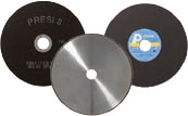
CUTTING
In other words, it is essential to avoid heating or any deformation of the metal that could lead to strain hardening. Cutting is a fundamental step which conditions the further preparation and inspection of parts.

=> Clamping, i.e. holding the workpiece, is essential. If the workpiece is not held properly, the cut can be detrimental to the cut-off wheel, the workpiece and the machine.
CONSUMABLES
 |
Stainless steel |
| Micro-cutting | UTW S Ø180 AO |
| Medium cutting | A AO |
| High-capacity cutting | A AO |
Table 1: Choosing the right cut-off wheel type

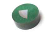
MOUNTING
Achieving good-quality mounting is essential to protect fragile materials and also to achieve good preparation results for polishing and future analysis.
Before mounting, the specimen should be deburred with coarse abrasive paper, for example, to remove any cutting burrs. Cleaning with ethanol (in an ultrasonic tank for even greater efficiency) is also possible. This allows the resin to adhere as well as possible to the sample and thus limits shrinkage (space between the resin and the sample).
If shrinkage persists, it can lead to problems during polishing. Abrasive grains may become lodged in this space and then be released at a later stage, thus creating a risk of pollution for the sample and the polishing surface. In this case, cleaning with an ultrasonic cleaner between each step is recommended.
There are two mounting options:
HOT MOUNTING
• Fully automatic hot-mounting press.
• Easy to use: memorisation, adjustment of processes and speed of execution make it a high-precision machine,
• The hot-mounting machine has 6 different mould diameters from 25.4-50mm.
+ POINT
COLD MOUNTING
• If the parts to be examined are fragile/sensitive to pressure
• If they have a complex geometry such as a honeycomb structure.
• If a large number of parts are to be mounted in series.
The cold process can be used with:
+ POINT
+ POINT
CONSUMABLES
 |
Stainless steel |
| Hot process | Hot Epoxy Phenolic Allylic |
| Cold process | IP KM-U KM-B 2S* |
Table 2: Choosing the right mounting resin type
* Suitable for very large series

POLISHING
PRESI offers a wide range of manual and automatic polishing machines, with a wide choice of accessories, to cover all needs, from pre-polishing to super-finishing and polishing of single or series samples.
The MECATECH range of automatic polishers allows both manual and automatic polishing. With its advanced technologies, motor power from 750-1500 W, all the PRESI experience is concentrated in this very complete range. Whatever the sample number or size, MECATECH guarantees optimal polishing.
CONSUMABLES AND POLISHING RANGE
All the first steps of each range are called “levelling” and consist of removing material quickly to level the surface of the sample (and resin). Those given below are standard and can therefore be modified as required.
Applied pressures vary according to sample size, but in general the following applies: 1daN per 10mm mounting diameter for the pre-polishing steps (ex: Ø40mm = 4 daN) then reduce force by 0.5daN at each polishing step with an abrasive suspension.
RANGE N°1
| N° | Support | Suspension / Lubricant |
Platen speed (RPM) |
Head speed (RPM) |
Rotation direction platen / head |
Time |
| 1 | SiC P320 | Ø / Water | 300 | 150 | 1’ | |
| 2 | SiC P1200 | Ø / Water | 300 | 150 | 1’ | |
| 3 | RAM | 3μm LDP / Reflex Lub |
150 | 135 | 2’ | |
| 4 | NT | 1μm LDP / Reflex Lub |
150 | 135 | 1’ | |
| 5 | NT | Al2O3 n°3 / Water |
150 | 100 | 1’ |
RANGE N°2
| N° | Support | Suspension / Lubricant |
Platen speed (RPM) |
Head speed (RPM) |
Rotation direction platen / head |
Time |
| 1 | I-Max R 54μm | Ø / Water | 300 | 150 | 3’ | |
| 2 | I-Max R 18μm | Ø / Water | 300 | 150 | 3’ | |
| 3 | ADR II | 3μm LDP / Reflex Lub |
150 | 135 | 4’ | |
| 4 | NT | 1μm LDP / Reflex Lub |
150 | 135 | 1’ | |
| 5 | NT | Al2O3 n°3 / Water |
150 | 100 | 1’ |
RANGE N°3
| N° | Support | Suspension / Lubricant |
Platen speed (RPM) |
Head speed (RPM) |
Rotation direction platen / head |
Time |
| 1 | SiC P80 | Ø / Water | 300 | 150 | 1’ | |
| 2 | MED R | 9μm super abrasive / Ø | 150 | 135 | 3’ | |
| 3 | ADR II | 3μm LDP / Reflex Lub |
150 | 135 | 1’ | |
| 4 | NT | 1μm LDP / Reflex Lub |
150 | 135 | 1’ | |
| 5 | NT | Al2O3 n°3 / Water |
150 | 100 | 1’ |
 |
RANGE N°1 | RANGE N°2 | RANGE N°3 |
| Stainless steels | All | Treated (hard) | All |
| Benefits | Flexible | • Long lasting consumables • Optimised for large series • Excellent flatness |
Quick, reduced number of steps |
Table N°3: Choice of range
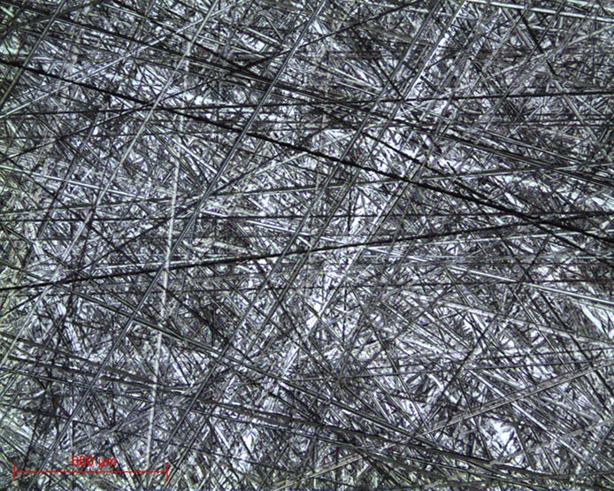
At the end of this preparation, the polished specimens can be directly inspected without metallographic etching. Otherwise, metallographic etching is commonly carried out using the ADLER reagent. It can also be done with MARBLE or KALLING reagents. Etching creates differences in relief and/or colour between the different constituents, thus allowing inspection.

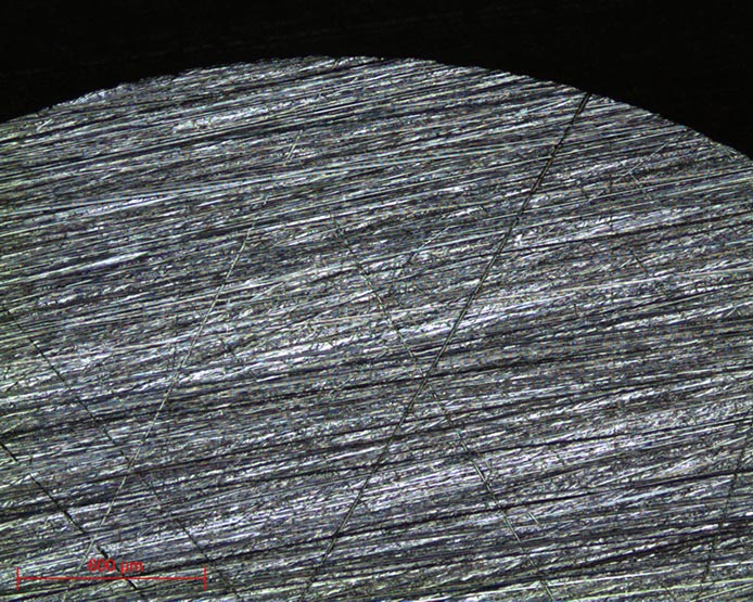
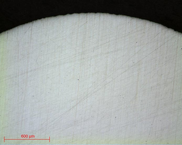
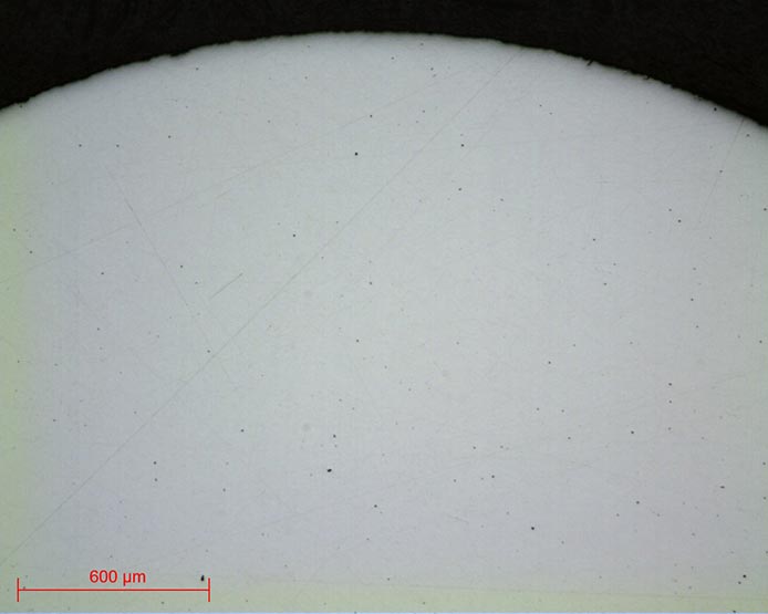
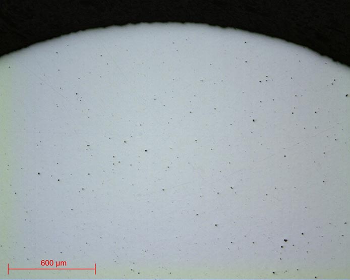
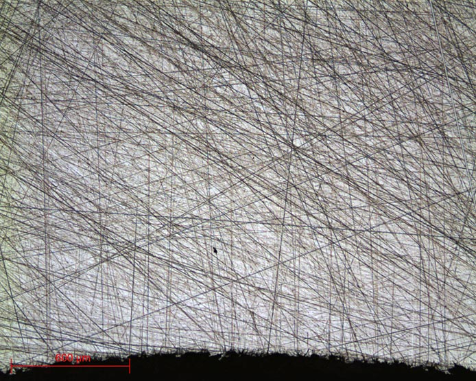
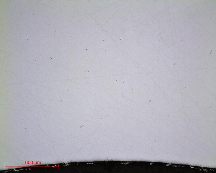
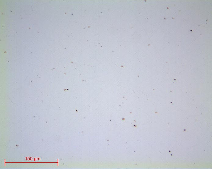
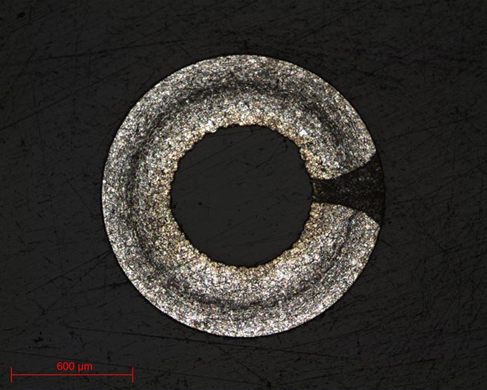
MICROSCOPY
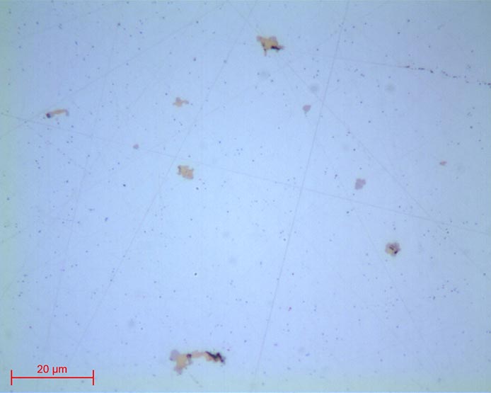
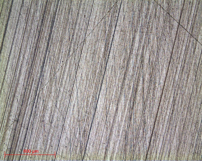
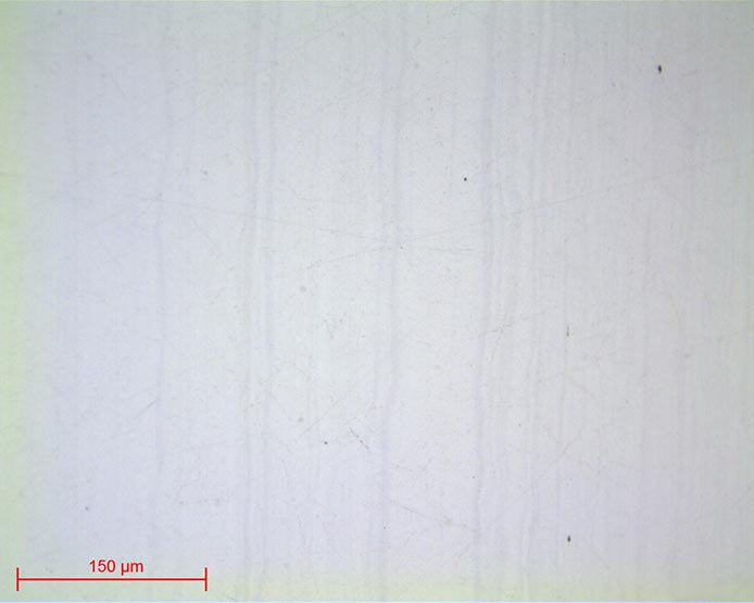
Micrographs 13 and 14:
Stainless steel polished up to 1μm lens x20 and x100
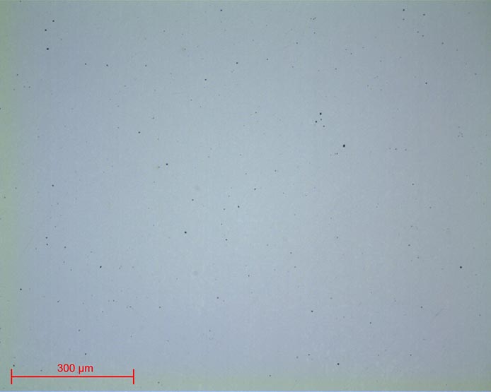
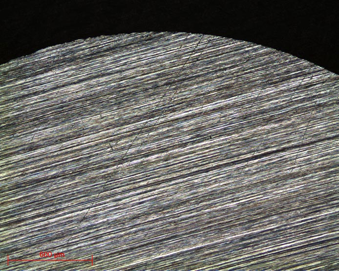
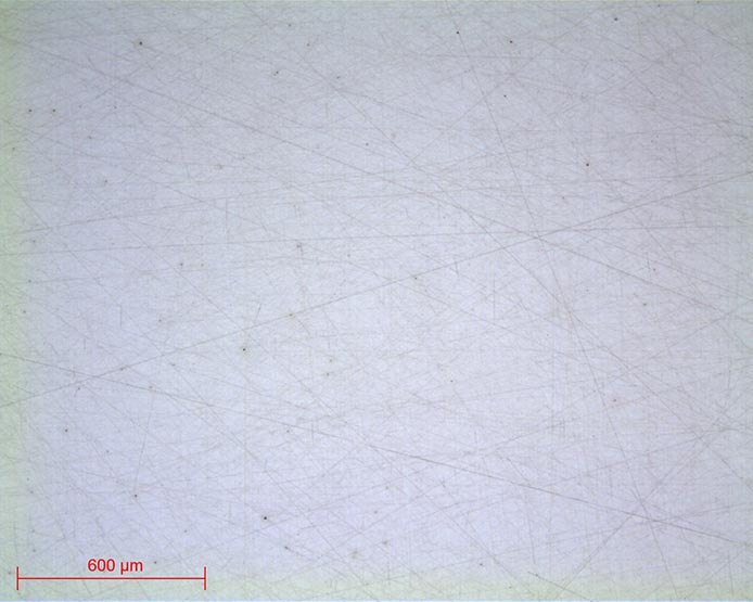
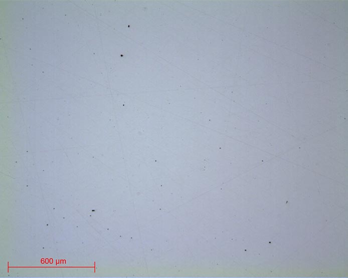
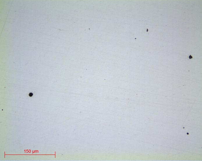
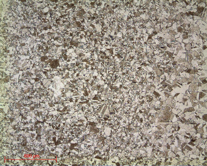
Micrographs 15 and 16:
Stainless steel polished up to Al2O3 N°3 lens x10 and x50
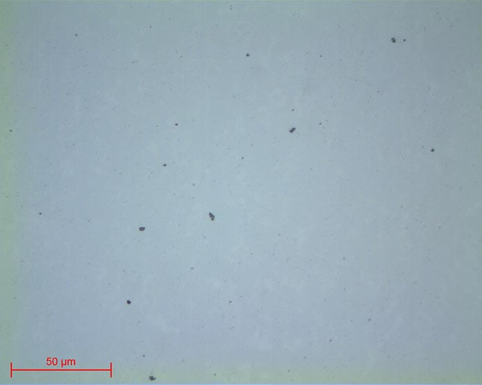
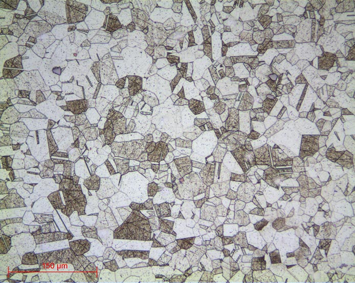
Micrographs 17 and 18:
Stainless steel polished up to Al2O3 N°3 lens x20
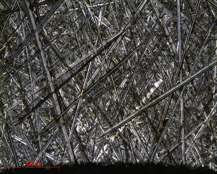
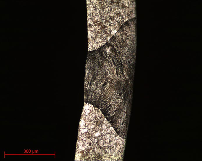
Micrographs 19 and 20:
Stainless steel etched with ADLER lens x5 and lens x20
DOWNLOAD THE LAB'NOTE
Simply fill out the form below:
Discover our other Lab’Note:
- 3D printing quality control
- Hardened heat treatment control
- Medical device quality control
- Steel quality control
- Stainless steel quality control
- Cast iron quality control
- Copper alloy quality control
- Aluminum quality control
- Nickel quality control
- Titanium quality control
- Ceramic materials quality control
- Electronics quality control
- Precious metal quality control