3D PRINTING QUALITY CONTROL


INTRODUCTION
This manufacturing process differs greatly from the usual techniques for producing parts. Additive manufacturing proceeds by adding material while machining proceeds by removing material. Therefore, no specific tool is required for 3D printing (cutting tool or mould, for example).
3D printing can be classified into three different processes. Whichever process is used, the principle is always the same. Firstly, designing a 3D digital model of the part and then transmitting the instructions in machine language (G code) to the printer, which then creates the part by adding layers of material.
These three categories of processes are:
MATERIAL DEPOSITION
SOLIDIFICATION USING LIGHT
Upon contact with ultraviolet light, the polymer cures instantly, the first layer is applied, the platform is lowered and the production of the second layer can begin. This operation is repeated until the part is complete. The platform then rises to the surface, revealing the product. The par polymerisation.
Selective Laser Sintering (SLS), also uses a laser beam, but this time a very powerful laser beam capable of rapidly raising the temperature of the material. The principle is therefore to heat in order to assemble the powder particles at very precise points and thus alloy them together. A new layer is then deposited and heated again to fuse with the previous one. This operation is repeated until the finished part is obtained. The most common material is polyamide (nylon) but glass powder or ceramics can also be used.
POWDER AGGLOMERATION BY GLUING
The processes mentioned above are adapted and developed mainly for the printing of polymer parts. Nevertheless, additive metal manufacturing has been gained momentum in recent years and has undergone numerous technological developments. These advances allow more and more innovative manufacturing methods and generate a wider range of usable materials. Among the additive metal manufacturing processes we find mainly:
Direct Metal Laser Sintering (DMLS), part of the 3D printing family called “powder bed fusion”. This method is based on the same principle as the SLS process, i.e. precise heating by means of a laser beam to sinter or fuse metal powder particles together and thus produce the final part layer by layer.
Direct Laser Additive Construction (DLAC): concentrated energy material deposition technology. It consists of feeding material in the form of metal powder or wire through the printer nozzle and immediately melting it at the outlet using a powerful heat source: in this case a laser beam (other technologies exist for which heating is provided by an electron beam – EBM – or plasma). This method allows direct printing of parts, unlike with the powder bed melting process.
Cold Spray: the aim is to coat a part by cold metallization. The metal powder particles are sprayed in a gas (nitrogen or helium) under pressure (approximately 50 bars) at very high speed (up to 1200m/s) onto the substrate. Upon impact, particle deformation ensures the quality of the deposit.
Stratoconception is a hybrid 3D printing process which breaks down the part to be produced into several layers. Each of the layers is created by some form of cutting (milling, laser cutting, wire sawing, etc.), which are then positioned using inserts, bridges or other nesting elements in order to be assembled and thus reconstitute the final part.
=> Various other technologies have been developed directly by some manufacturers. All these developments further distinguish the process categories already mentioned.
Most metals can be used in additive manufacturing. The most widespread are aluminium (often in the form of an alloy) for its lightness, and steel for its mechanical properties. Titanium, cobalt-chromium, gallium, superalloys (inconel type) and precious metals (gold, platinum and silver) are also widely used in this industry.
However, it is important to note that metallic powders are expensive, so 3D printing is not used in the manufacture of very large parts.
The field of 3D printing is a rapidly evolving one. It offers major advantages but also presents some limitations. The advantages include:
– The ability to manufacture parts with complex geometries without increasing costs. The manufacturing process whereby layers are added makes it possible to achieve precise part geometries more easily than by “traditional” manufacturing, sometimes even at a lower cost because less material is used.
– No specific tooling is required to create a product (as opposed to the tooling devices or moulds used in shapes manufacturing). The cost of a 3D printed part depends solely on the amount of material used, the time required to produce it and the subsequent processing operations.
– The ease of creating customised parts. As start-up costs are low, each production can be personalised simply by modifying the 3D digital model.
– Rapid prototyping at low cost. The rapidity of part manufacture greatly accelerates the “design cycle” (design, testing, improvement, modification, etc.).
– The wide range of usable materials. Although the most commonly-used materials are plastics, metals and composites are finding more and more industrial applications to meet ever more specific needs.
Nevertheless, 3D printing in manufacturing presents some limitations:
– For most 3D printing processes the physical properties of the products are not as good as those of the materials used.
However, selective metal melting by laser processes (DMLS) do in some cases produce parts with excellent mechanical properties.
– Additive manufacturing is limited by the number of products to be mass-produced. It cannot compete with other processes for very large production runs.
– The tolerance and precision of parts are limited. They vary according to the printing process, but the parts often require finishing operations to optimise characteristics, tolerances and surface finishes. 3D-printed parts are rarely ready for use when they come off the “printer”. The finishing operations required are usually the removal of the substrate (i.e. all the printed structures to anchor the part and/or make up for imbalance during printing), sanding, polishing, painting, etc.
=> 3D printing is therefore used in many industrial fields. It finds applications in many activity sectors such as: automotive (titanium brake calliper), aeronautics (lightening of structures), naval aviation (ship propellers), energy (gas turbine blades), medical (titanium implants), aerospace (telescopic aluminium mirror, satellite antenna support, rocket engine turbo pump), metal construction (steel bridge), watchmaking, jewellery or goldsmith’s trade, etc.
It is the additive metal fabrication that will most often require metallographic preparation.


METALLOGRAPHIC PREPARATION
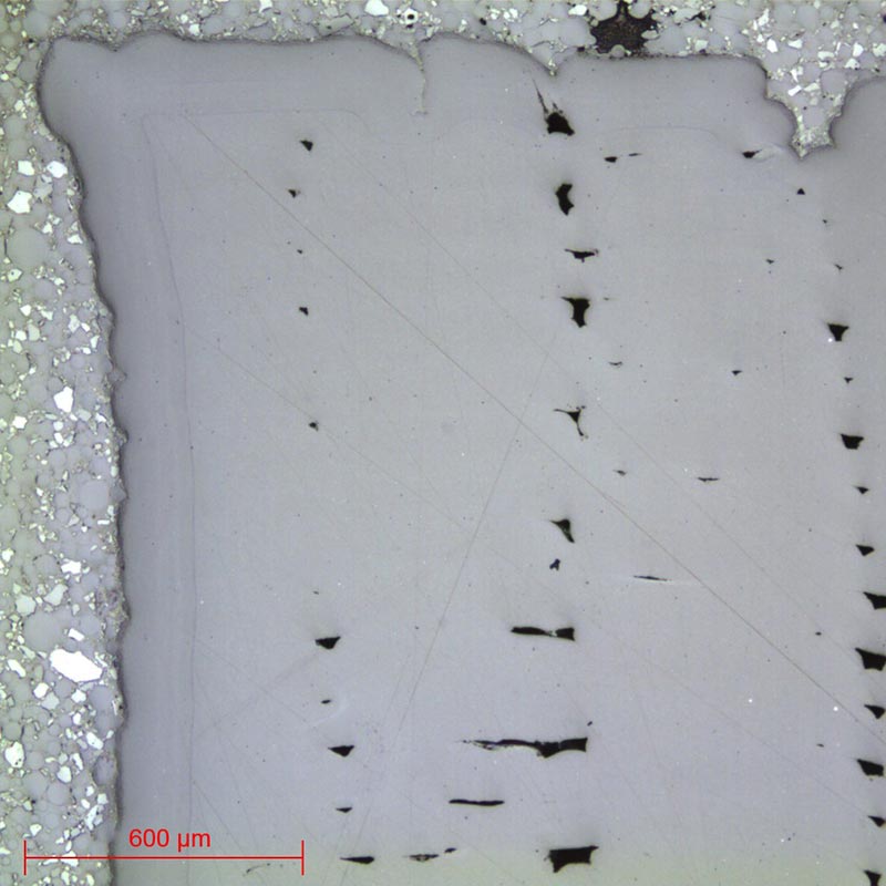
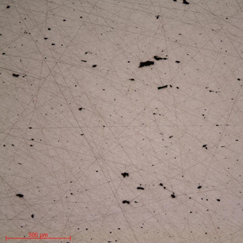
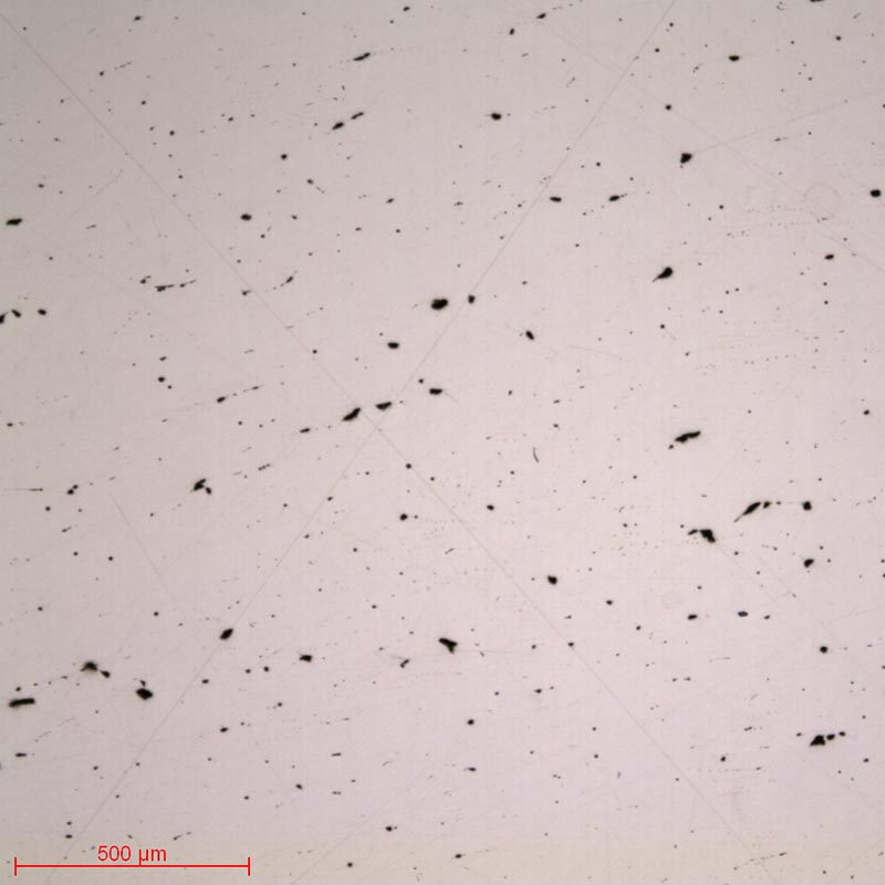
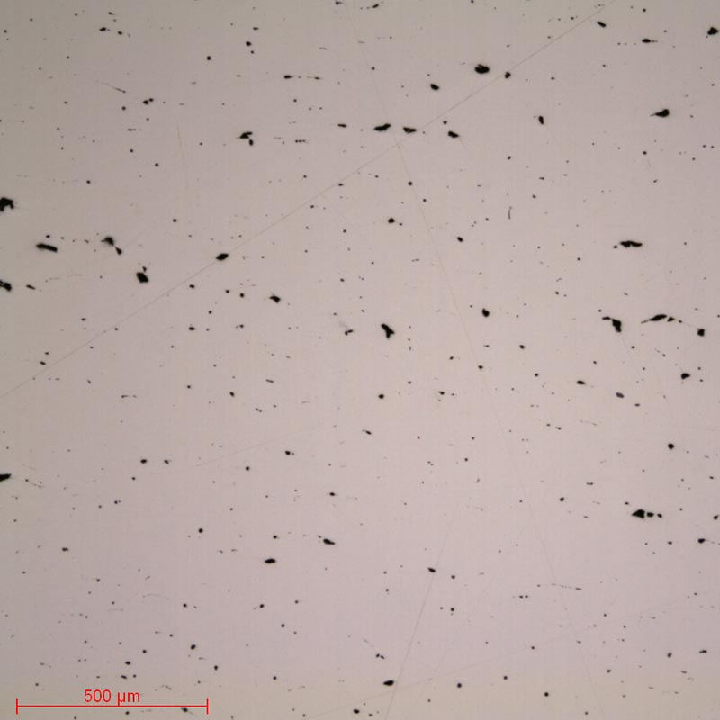
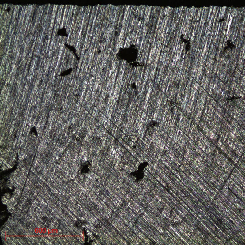
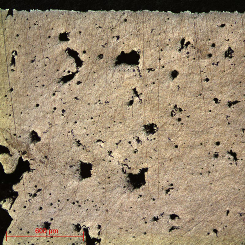
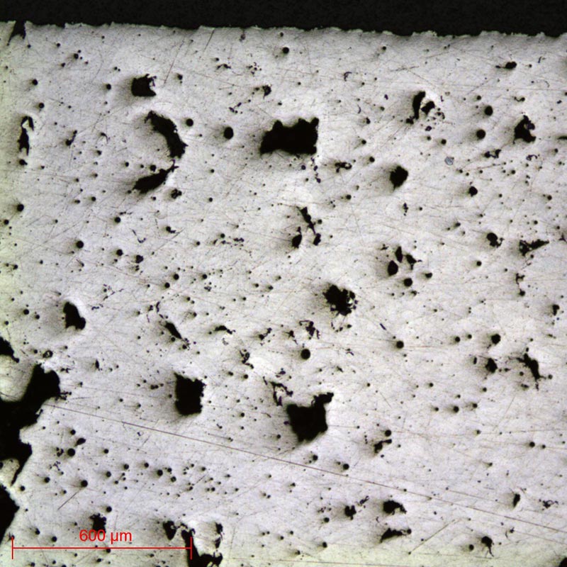
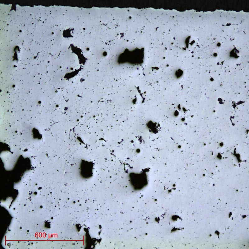
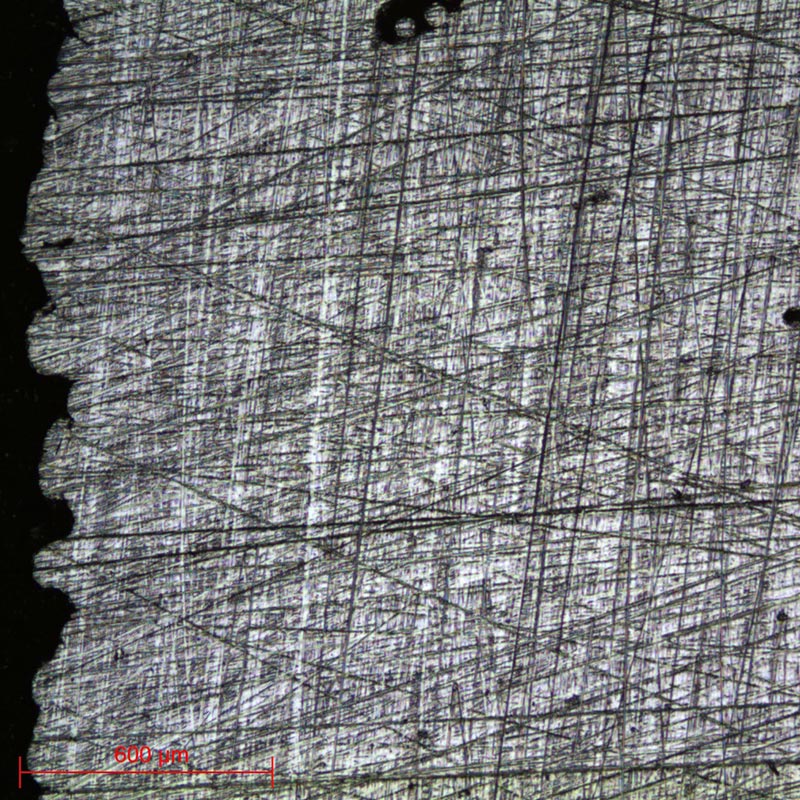
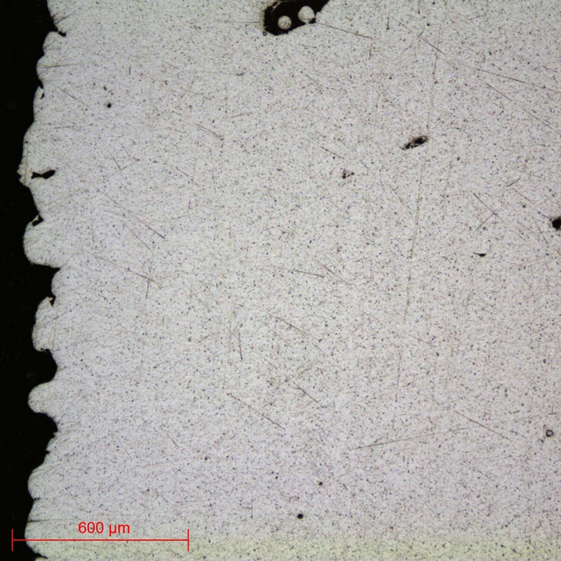
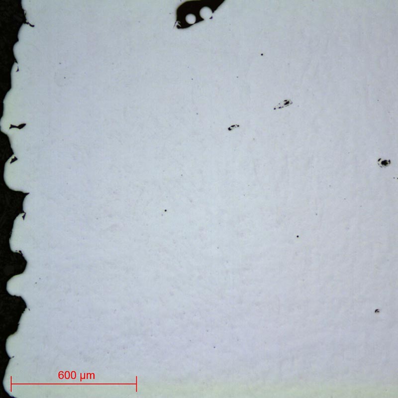
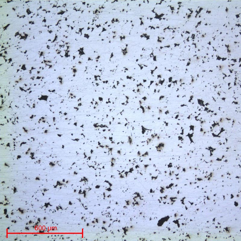
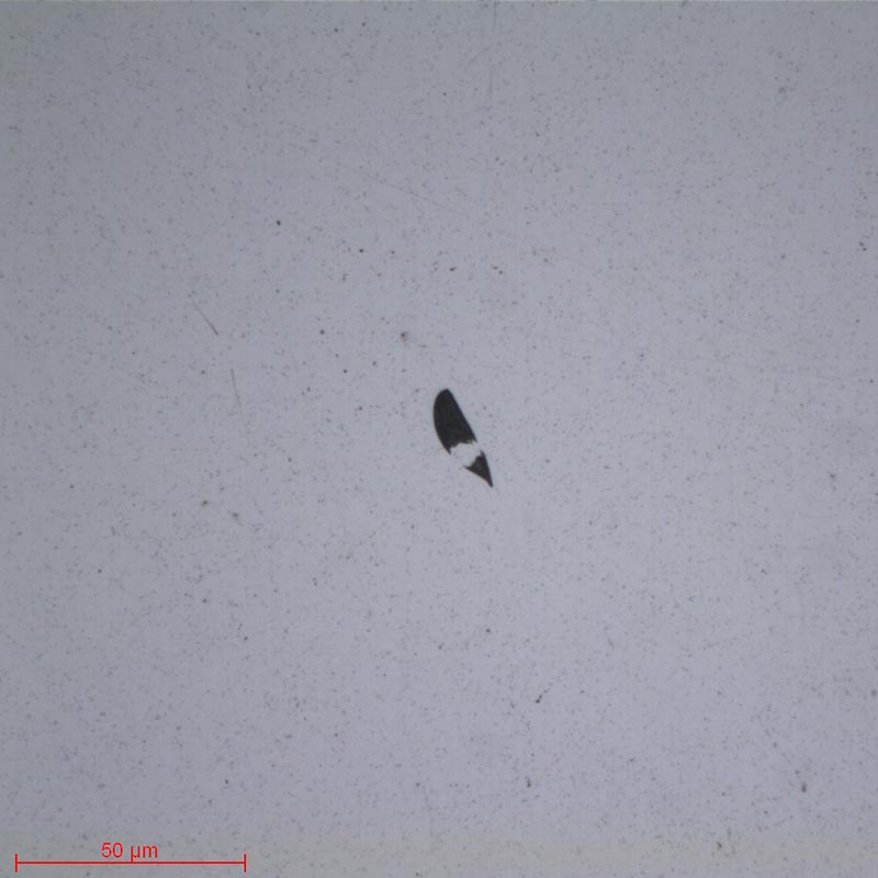
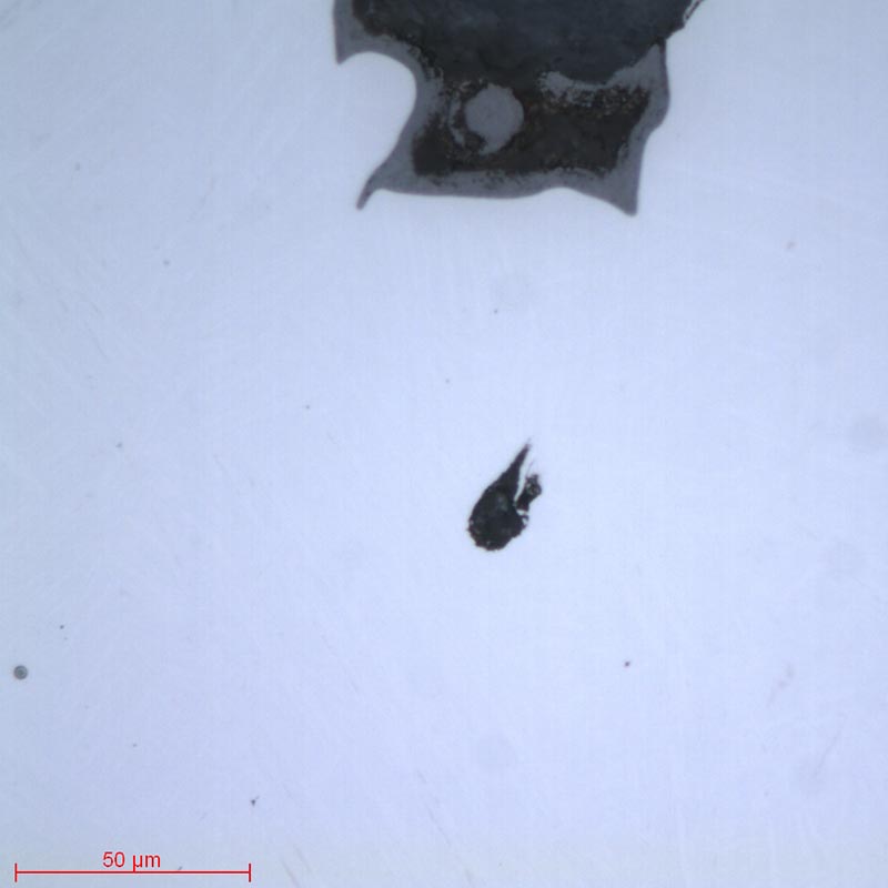
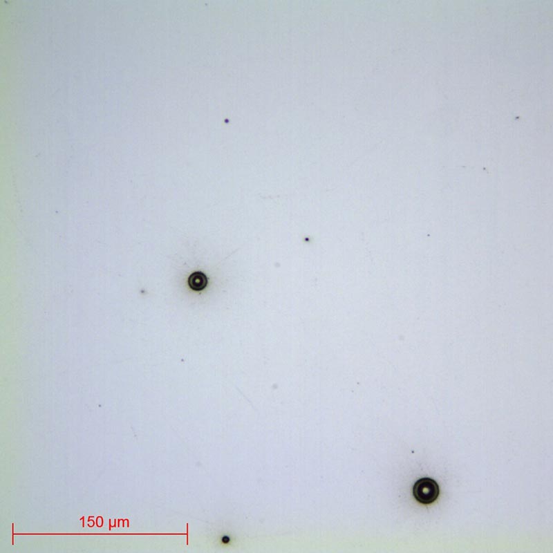
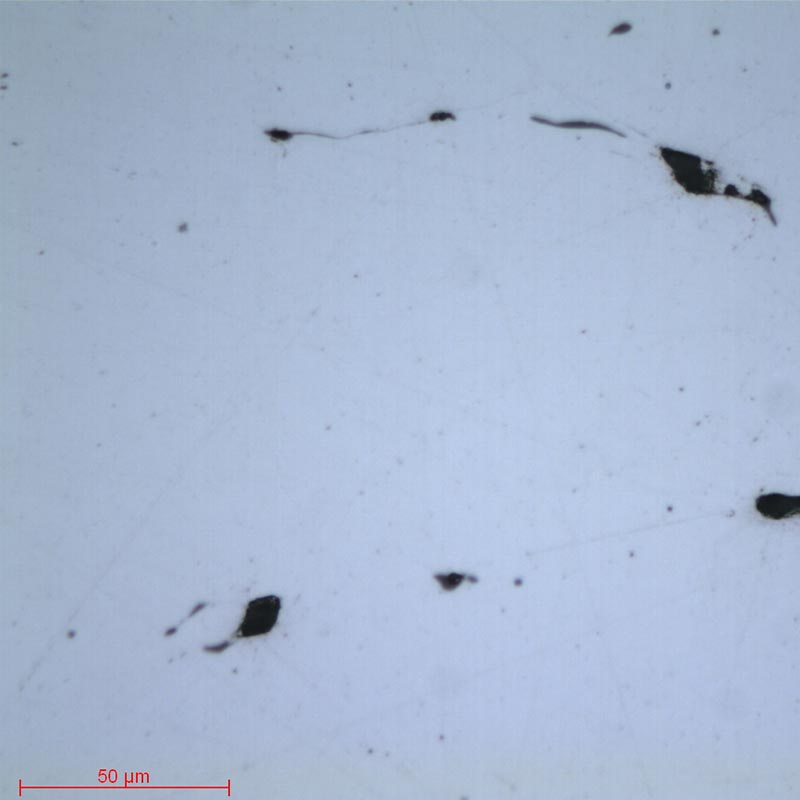
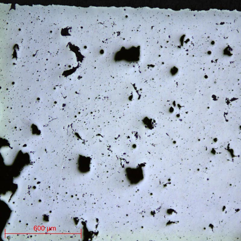
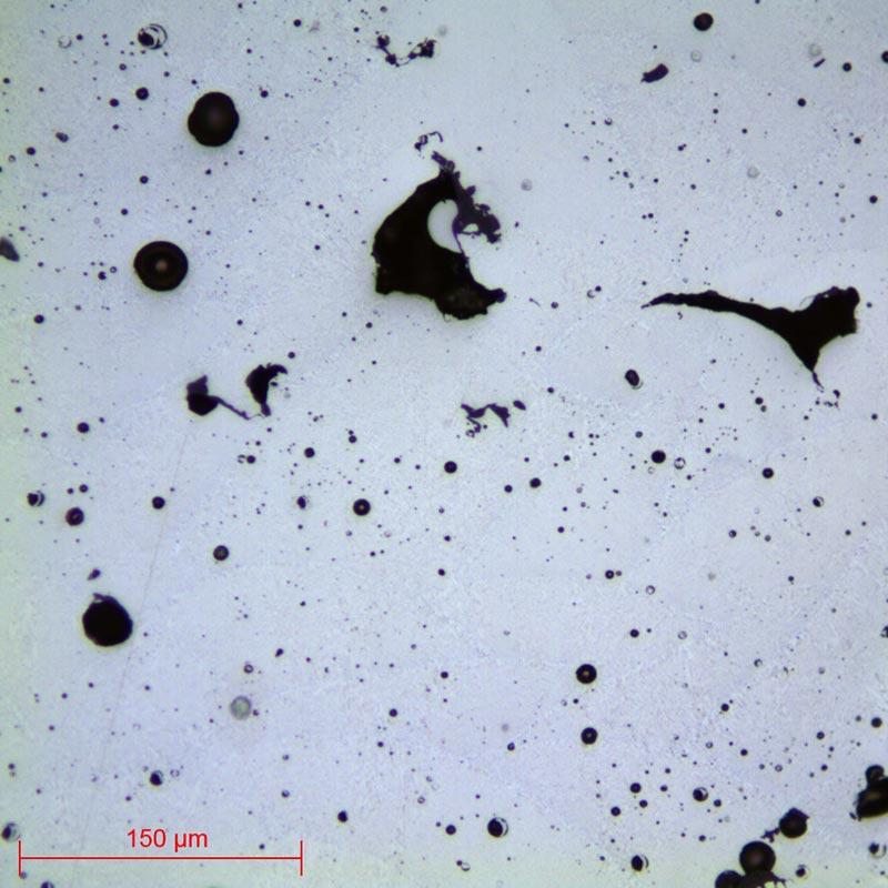
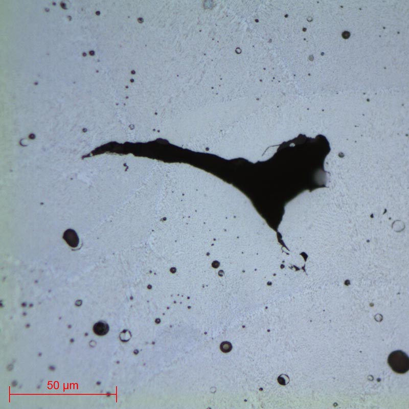
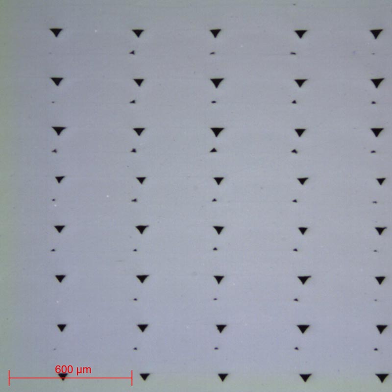
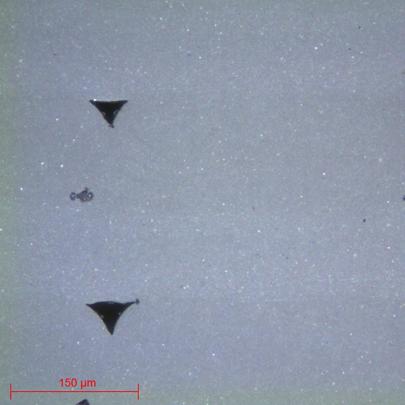
All these influences lead to metallographic quality controls such as: examinations of porosities, dimensioning, pull-out, structures and microstructures, searches for heterogeneities, search for and examination of inclusions and/or impurities, hardness tests, grain size controls, etc.
– The removal of the product to be examined (if necessary), called “CUTTING”.
– Standardisation of the geometry of the sample taken (if necessary), called “MOUNTING”.
– Improvement of the surface condition of this sample, called “POLISHING”.
– Characterisation of the sample: revealing the microstructure of the sample by an etching reagent (if necessary) called “METALLOGRAPHIC ETCHING” and microscopic observation (optical or electronic).
=> Each of these steps must be carried out rigorously, otherwise the following steps will not be possible.

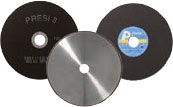
CUTTING
PRESI’s wide range of medium and large capacity cutting and micro-cutting machines can be adapted to any need with regard to cutting precision, sizing or quantity of products to be cut:

CONSUMABLES
The choice cut-off wheel type depends on the properties of the material and especially its hardness. It is therefore necessary to match consumables to the make-up of the composite material to be cut (see Lab’Notes corresponding to the material for more information). Consumables are chosen according to the majority material (polymer, light metal or ceramic).
 |
Polymer materials | Metallic materials | Ceramic materials | |
| Non-ferrous | Ferrous | |||
| Micro-cutting | UTW S Ø180 MNF LM+ LR |
UTW S Ø180mm MNF |
UTW S Ø180 A CBN |
LM / LM+ LR |
| Medium-capacity cutting | MNF LM+ LR |
T MNF F |
A AO S CBN |
LM / LM+ LR |
| High-capacity cutting | MNF LM+ LR |
T MNF |
A AO S CBN |
LM / LM+ LR |

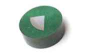
MOUNTING
=> Achieving good-quality mounting is essential to protect fragile materials and also to achieve good preparation results for polishing and future analysis.
Before mounting, the specimen should be deburred with coarse abrasive paper, for example, to remove any cutting burrs. Cleaning with ethanol (in an ultrasonic tank for even greater efficiency) is also possible. This allows the resin to adhere as well as possible to the sample and thus limits shrinkage (space between the resin and the sample).
If shrinkage persists, it can lead to problems during polishing. Abrasive grains may become lodged in this space and then be released at a later stage, thus creating a risk of pollution for the sample and the polishing surface. In this case, cleaning with an ultrasonic cleaner between each step is recommended.
There are two mounting options:
HOT MOUNTING
– Fully automatic hot-mounting press.
– Easy to use: memorisation, adjustment of processes and speed of execution make it a high-precision machine,
– The hot-mounting machine has 6 different mould diameters from 25.4-50mm.
+ POINT
COLD MOUNTING
– If the parts to be examined are fragile/sensitive to pressure
– If they have a complex geometry such as a honeycomb structure.
– If a large number of parts are to be mounted in series.
The cold process can be used with:
+ POINT
+ POINT
CONSUMABLES
 |
Polymer materials | Metallic materials | Ceramic materials |
| Hot process | Ø | Hot epoxy Phenolic Allylic |
Ø |
| Cold process | KM-U KM-B IP / IP-FAST MA2+ |
KM-U KM-B IP / IP-FAST 2S* |
KM-U KM-B IP / IP-FAST |
* Suitable for very large series

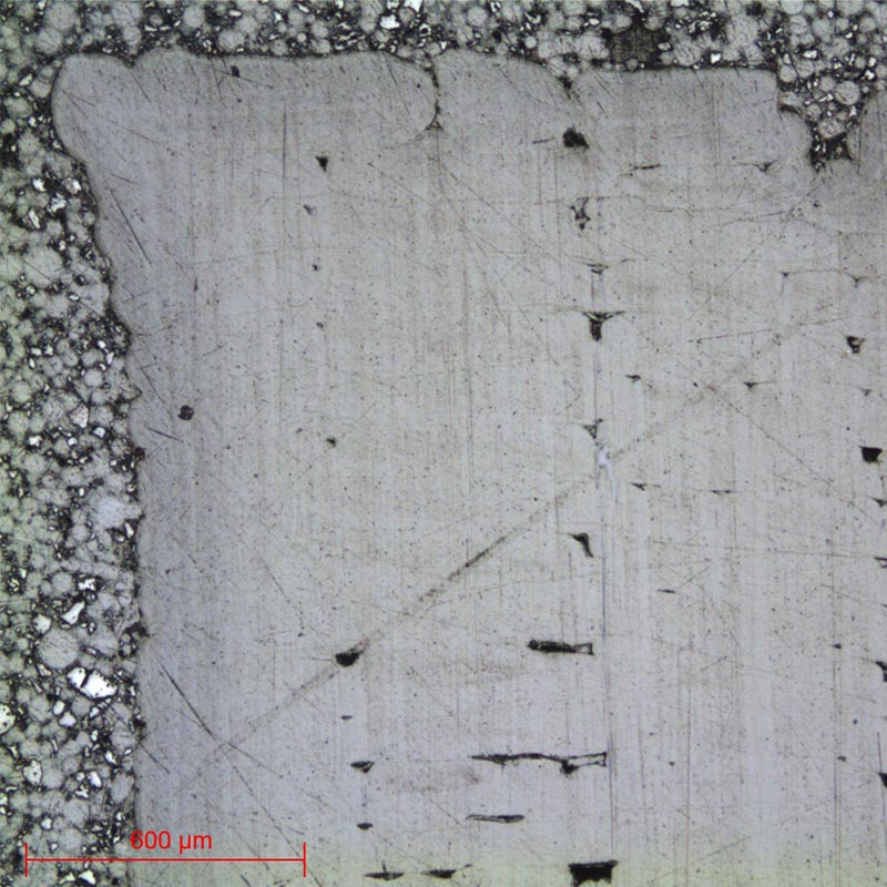
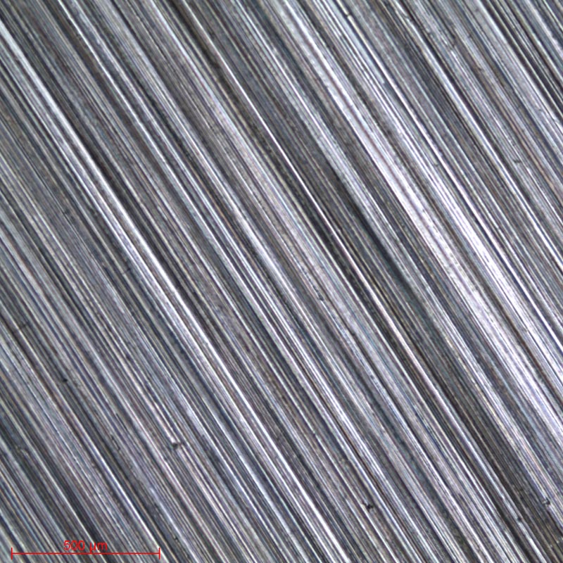
POLISHING
PRESI offers a wide range of manual and automatic polishing machines, with a wide choice of accessories, to cover all needs, from pre-polishing to super-finishing and polishing of single or series samples.
CONSUMABLES AND POLISHING RANGE
All the first steps of each range are called “levelling” and consist of removing material quickly to level the surface of the sample (and resin). Those given below are standard and can therefore be modified as required.
Applied pressures vary according to sample size, but in general the following applies: 1daN per 10mm mounting diameter for the pre-polishing steps (ex: Ø40mm = 4 daN) then reduce force by 0.5daN at each polishing step with an abrasive suspension.
| Range | N°1 | N°2 | N°3 | N°4 | N°5 |
| Material | Polymer materials | Steel and hard metals | Soft metals | Titanium | Ceramic materials |
Range N°1
| N° | Support | Suspension / lubricant | Platen Speed (RPM) | Head Speed (RPM) | Rotation direction plate / head | Time |
| 1 | SiC P600 | Ø / Water | 300 | 150 | 1’ | |
| 2 | TOP | 9μm LDP / Reflex Lub | 150 | 135 | 4’ | |
| 3 | STA | 3μm LDP / Reflex Lub | 150 | 135 | 3’ | |
| 4 | NT | Al2O3 n°1 / Water | 150 | 100 | 1’ |
Range N°2
| N° | Support | Suspension / lubricant | Platen Speed (RPM) | Head Speed (RPM) | Rotation direction plate / head | Time |
| 1 | SiC P320 | Ø / Water | 300 | 150 | 1’ | |
| 2 | TOP | 9μm LDP / Reflex Lub | 300 | 150 | 4’ | |
| 3 | RAM | 3μm LDP / Reflex Lub | 150 | 135 | 2’ | |
| 4 | NT | 1μm LDP / Reflex Lub | 150 | 135 | 1’ | |
| 5 | NT | Al2O3 n°3 / Water | 150 | 100 | 1’ |
Range N°3
| N° | Support | Suspension / Lubricant | Plateau Speed (RPM) | Head Speed (RPM) | Rotation direction plate / head | Time |
| 1 | SiC P320 | Ø / Water | 300 | 150 | 1’ | |
| 2 | SiC P120 | Ø / Water | 300 | 150 | 1’ | |
| 3 | RAM | 3μm LDP / Reflex Lub | 150 | 135 | 3’ | |
| 4 | NT | 1μm LDM / Reflex Lub | 150 | 135 | 1’ | |
| 5 | SUPRA | SPM / Water | 150 | 100 | 1’ |
Range N°4
| N° | Support | Suspension / Lubricant | Platen Speed (RPM) | Head Speed (RPM) | Rotation direction plate / head | Time |
| 1 | SiC P320 | Ø / Water | 300 | 150 | 1’ | |
| 2 | TOP | 9μm LDP / Reflex Lub | 150 | 135 | 5’ | |
| 3 | SUPRA | SPM / Water | 150 | 100 | 5’ |
Range N°5
| N° | Support | Suspension / Lubricant | Platen Speed (RPM) | Head Speed (RPM) | Rotation direction plate / head | Time |
| 1 | Tissediam 40μm | Ø / Water | 300 | 150 | 2’ | |
| 2 | Tissediam 20μm | Ø / Water | 300 | 150 | 2’ | |
| 3 | TOP | 9μm LDP / Reflex Lub | 150 | 135 | 5’ | |
| 4 | NWF+ | 3μm LDP / Reflex Lub | 150 | 135 | 2’ | |
| 5 | SUPRA | SPM / Water | 150 | 100 | 2’ |
Moreover, they are not necessarily to be carried out in their entirety; observations will define needs (except for titanium samples for which all the steps of the range must be performed).
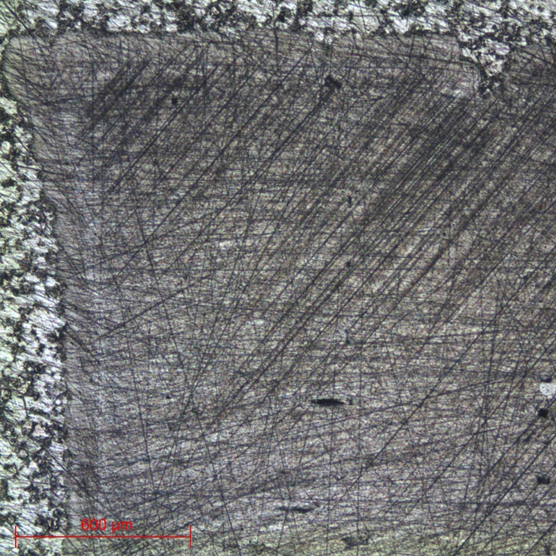
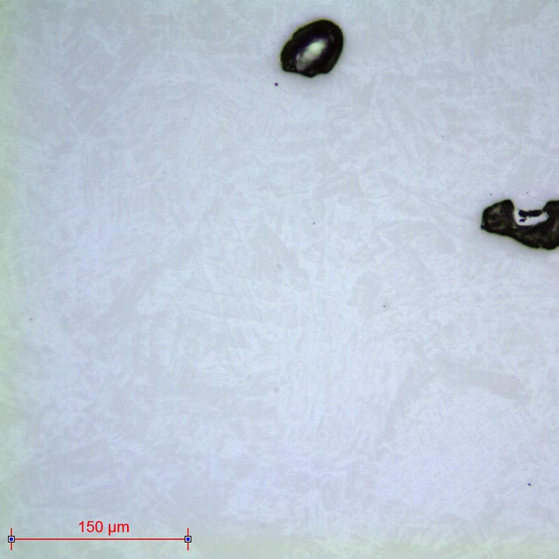
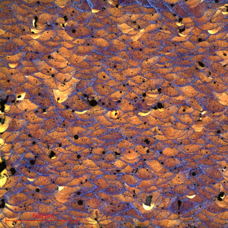
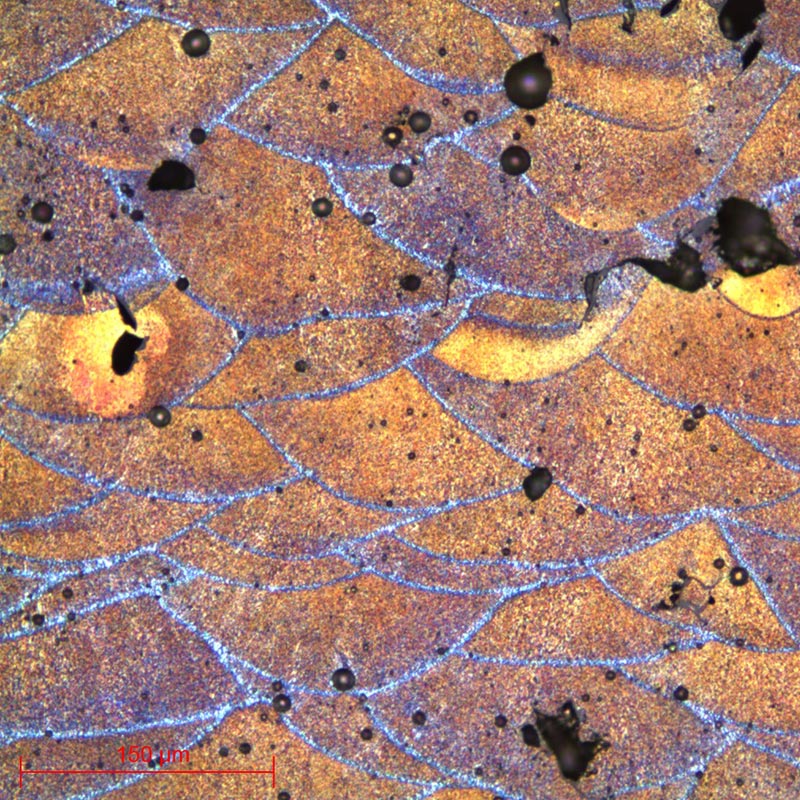
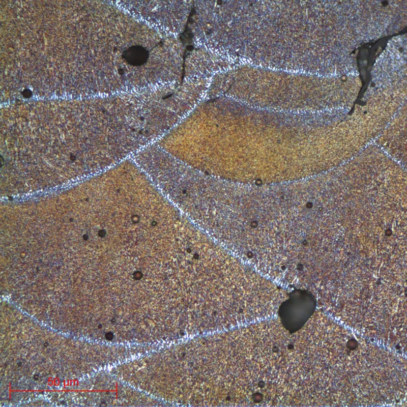
Otherwise, metallographic etching allows differences in relief and/or colour to be made between the different components and so allows them to be observed. It is mainly used on metals.

MICROSCOPY
DOWNLOAD LAB'NOTE
Simply fill in the form below:
Discover our other Lab’Note:
- 3D printing quality control
- Hardened heat treatment control
- Medical device quality control
- Steel quality control
- Stainless steel quality control
- Cast iron quality control
- Copper alloy quality control
- Aluminum quality control
- Nickel quality control
- Titanium quality control
- Ceramic materials quality control
- Electronics quality control
- Precious metal quality control