CAST IRON QUALITY CONTROL


INTRODUCTION

There is a second method for producing cast iron: from steel scrap and coke.
Different processes exist: cupola furnace, electric furnace or rotary furnace.

Fig. 1: Diagram of a blast furnace
• Hypoeutectic cast irons with less than 4.3 % carbon
• Eutectic cast irons with 4.3% carbon
• Hypereutectoid cast irons with more than 4.3% carbon
The Fe-C phase diagram (Figure 2) helps to explain solidification from the liquid state.

Fig. 2: Fe-C diagram
THE MAIN CAST IRONS
WHITE CAST IRONS
The carbon is in the form of Fe3C carbide with a pearlitic matrix. Its name comes from the fact that when broken, it has a shiny white metallic appearance. White cast iron is a cast iron alloyed with manganese. The presence of chromium and molybdenum also favours the creation of white cast iron. This type of cast iron is resistant to wear and tear but is fragile to impacts.
GREY CAST IRONS
Carbon appears in the form of (spheroidal or lamellar) graphite. These cast irons are rich in silicon; this alloy addition favours the formation of graphite. It also improves corrosion resistance.
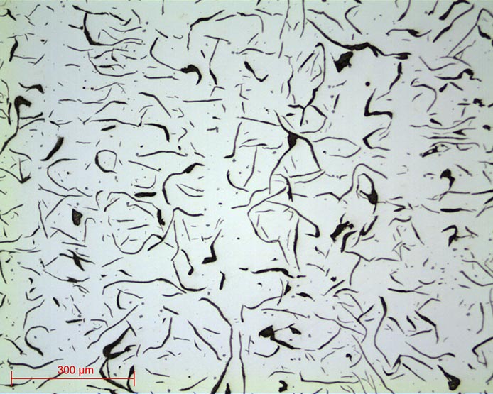
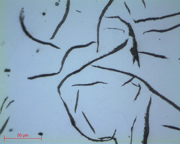
=> Lamellar graphite cast irons are brittle due to the geometry of the graphite which has a notch effect. Tensile strength is not optimal but it is suitable for compression work applications or if wear resistance is required.
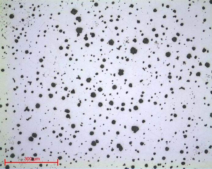
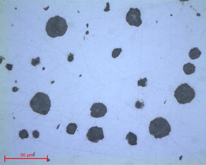
=> Spheroidal graphite cast irons are cast irons in which the cooling has been slowed down so that the carbon crystallises in the form of a sphere. The geometry of the graphite improves machinability and the mechanical characteristics are close to those of steel. It produces a ductile, malleable cast iron. The addition of magnesium in the cast iron reduces the presence of sulphur. Thus, the graphite is formed spherically and not in lamellae.
It is possible to create spheroidal graphite cast iron from white cast iron if subjected to heat treatment.
In alloyed cast irons:
• chromium increases the mechanical characteristics
• molybdenum improves impact resistance
• phosphorus gives the cast iron better castability.
The chemical composition of the mixture is one of the parameters that will determine the type of cast iron obtained.
Cooling speed influences the formation of one or other of the cast irons.
• If the cooling is quick, it favours the formation of cementite, thus producing a white cast iron.
• However, if cooling is slower, the carbon has time to collect as graphite, producing grey cast iron.
CAST IRON DESIGNATIONS
Their designation always starts with EN-GJ (G corresponds to a cast metal and J for iron).
Another letter corresponding to the structure of the graphite follows this beginning of the designation:
L for Lamellar
S for Spheroidal
M for annealed graphite (malleable)
V for vermicular
Y for special structure
N for no graphite
Generally, this is followed by either the required minimum tensile strength and minimum elongation in %, or the same designation as a high-alloy steel
Two examples:
EN-GJS-400-15: Lamellar graphite cast iron, strength R min 400 MPa and elongation A 15%.
EN-GJN-X 300 Cr Ni Si 9-5-2: Graphite-free cast iron (white cast iron) with 3% carbon, 9% chromium, 5% nickel and 2% silicon
=> They are available in a wide range of cast iron grades to meet all applications according to the properties of impact resistance, wear resistance and good castability.
APPLICATIONS

METALLOGRAPHIC PREPARATION
• Standardisation of the geometry of the sample taken (if necessary), called «MOUNTING».
• Improvement of the surface condition of this sample, called «POLISHING».
• Sample characterisation: to reveal the microstructure of the sample by an etching reagent (if necessary) called «METALLOGRAPHIC ETCHING» and microscopic observation (optical or electronic).

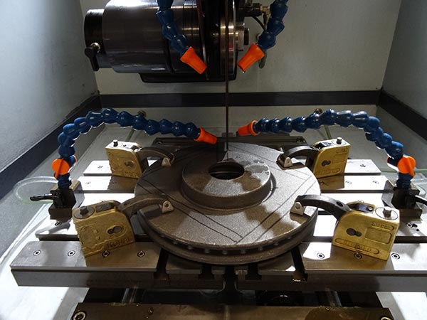
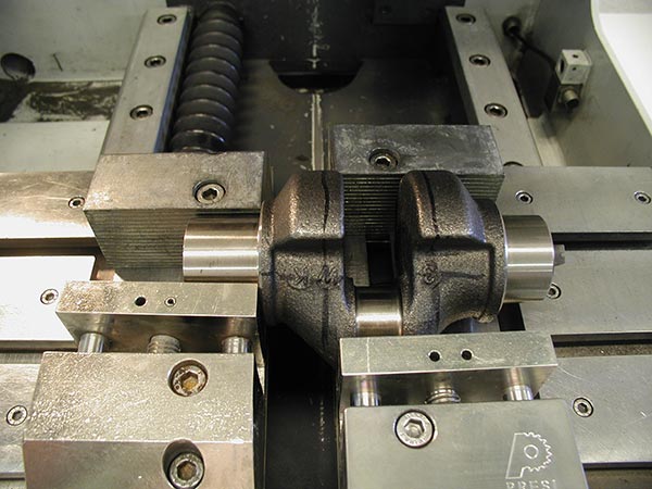
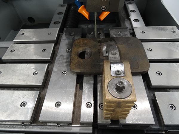
CUTTING
In other words, it is essential to avoid heating or any deformation of the metal that could lead to degradation of the material. Cutting is a fundamental step which conditions the further preparation and inspection of parts.
PRESI’s wide range of medium and large capacity cutting and micro-cutting machines can be adapted to any need with regard to cutting precision, sizing or quantity of products to be cut:

CONSUMABLES
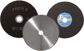 |
GREY IRON | WHITE CAST IRON |
| Micro-cutting | S (Ø 180mm) UTW |
S (Ø 180mm) AO CBN |
| Medium-capacity cutting | F MNF AO |
F AO CBN |
| High-capacity cutting | MNF AO |
AO |
Table 1: Choosing the right cut-off wheel type

MOUNTING
Achieving good-quality mounting is essential to protect fragile materials and also to achieve good preparation results for polishing and future analysis.
Before mounting, the specimen should be deburred with coarse abrasive paper, for example, to remove any cutting burrs. Cleaning with ethanol (in an ultrasonic tank for even greater efficiency) is also possible. This allows the resin to adhere as well as possible to the sample and thus limits shrinkage (space between the resin and the sample).
There are two mounting options:
HOT MOUNTING
• Fully automatic hot-mounting press.
• Easy to use: memorisation, adjustment of processes and speed of execution make it a high-precision machine,
• The hot-mounting machine has 6 different mould diameters from 25.4-50mm.
+ POINT
COLD MOUNTING
• If the parts to be examined are fragile/sensitive to pressure
• If they have a complex geometry such as a honeycomb structure.
• If a large number of parts are to be mounted in series.
The cold process can be used with:
+ POINT
+ POINT
CONSUMABLES
The cold process has different mounting moulds with diameters from 20-50mm. These are divi- ded into several types: optimised moulds called «KM2.0», rubber, Teflon or polyethylene moulds. Cold mounting is also more flexible, hence the existence of rectangular moulds for more specific needs.
 |
WHITE AND GREY IRON |
| Hot process | Phenolic Allylic Hot Epoxy |
| Cold process | KM-B KM-U |
Table 2: Choosing the right mounting resin type

POLISHING
PRESI offers a wide range of manual and automatic polishing machines, with a wide choice of accessories, to cover all needs, from pre-polishing to super-finishing and polishing of single or series samples.
The MECATECH range of automatic polishers allows both manual and automatic polishing. With its advanced technologies, motor power from 750-1500 W, all the PRESI experience is concentrated in this very complete range. Whatever the sample number or size, MECATECH guarantees optimal polishing.
CONSUMABLES AND POLISHING RANGES
All the first steps of each range are called «levelling» and consist of removing material quickly to level the surface of the sample (and resin). Those given below are standard and can therefore be modified as required.
Applied pressures vary according to sample size, but in general the following applies: 1daN per 10mm mounting diameter for the pre-polishing steps (ex: Ø40mm = 4 daN) then reduce force by 0.5daN at each polishing step with an abrasive suspension.
The following is a general polishing range for cast iron:
| N° | Support | Suspension / Lubricant | Platen speed (RPM) |
Head speed (RPM) |
Rotation direction platen / head |
Time |
| 1 | P320 | Ø / Water | 300 | 150 | 1’ | |
| 2 | TOP | 9μm ADS poly / Lub ADS | 150 | 135 | 4’ | |
| 3 | STA | 3μm ADS poly / Lub ADS | 150 | 135 | 3’ | |
| 4 | TFR | 1μm ADS poly / Lub ADS | 150 | 135 | 1’ |
NB: Levelling with P320 abrasive paper is sufficient for a sample from a metallographic cut. If more material removal is required, a larger grit-size should be used.
For pre-polishing, the head and plate rotation direction should not be reversed, as this can detrimentally affect flatness. However, reversing rotation direction can help if a large amount of material has to be removed.
Cast iron polishing can be performed using a mono-crystalline diamond suspension (alcohol-based, water-free). This prevents oxidation of the cast iron, which is sensitive to water during the finishing polishing steps.
When cleaning between steps, rapid drying with compressed air after cleaning with water is recommended, or cleaning with ethanol to limit the emergence of corrosion points.
| N° | Support | Suspension / Lubricant | Platen speed (RPM) |
Head speed (RPM) |
Rotation direction platen / head |
Time |
| 1 | I-Max R 54μm | Ø / Water | 300 | 150 | 3’ | |
| 2 | MED-R | 9μm super abrasive MED-R | 150 | 135 | 4’ | |
| 3 | STA | 3μm ADS poly / Lub ADS | 150 | 135 | 3’ | |
| 4 | TFR | 1μm ADS poly / Lub ADS | 150 | 135 | 1’ |
In this second range, levelling is performed using a 54μm I-Max R instead of abrasive paper. This resin-bonded diamond disc, suitable for polishing hard materials, maintains good flatness and can replace several hundred abrasive papers.
The second stage is performed using a MED-R disc. This support comprising resin pads, to which a super abrasive suspension for MED-R is added, maintains good flatness and offers a longer service life than a polishing cloth.
The finishing stages are performed using ADS suspension. A concentrated LDP polycrystalline suspension can sometimes be suitable, if the cast iron does not corrode or does so only slightly.

MICROSTRUCTURE
• Nital reagent 4%
• Picral’s reagent
• Chatelier’s reagent
The list is non-exhaustive; as cast irons structures are close to that of steel, some reagents are common to both materials. All the micrographs presented were created using the PRESI VIEW software:
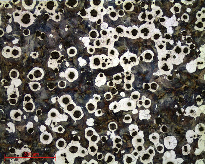
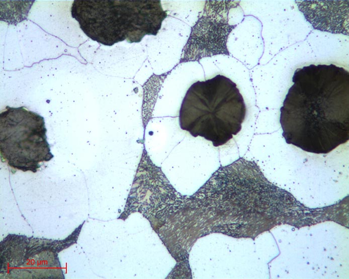
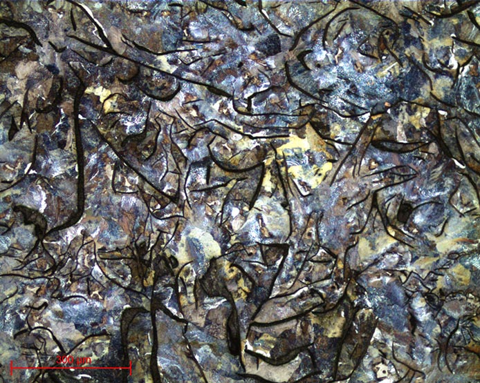
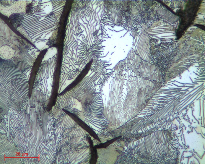
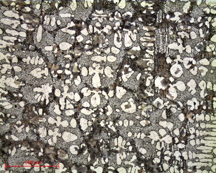
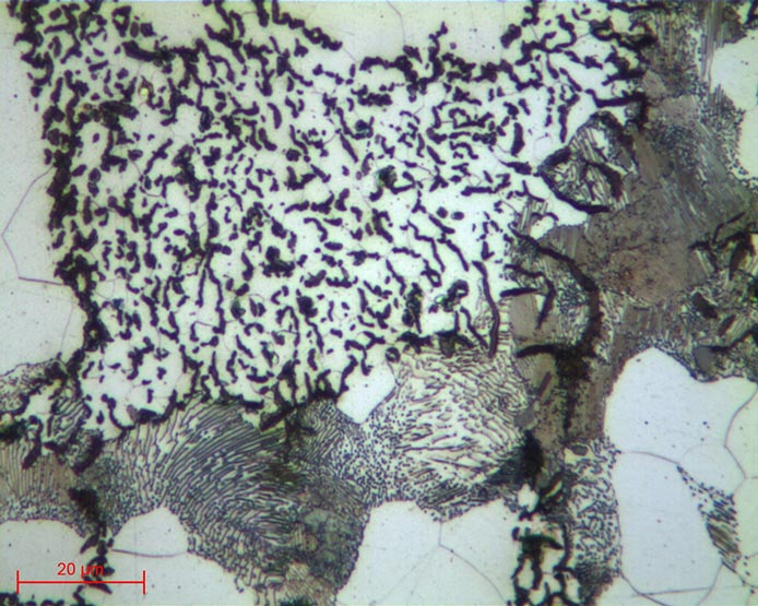
=> All the structures appearing in figures 17-22 were revealed using 4% Nital reagent.
DOWNLOAD THE LAB'NOTE
Simply fill out the form below:
Discover our other Lab’Note:
- 3D printing quality control
- Hardened heat treatment control
- Medical device quality control
- Steel quality control
- Stainless steel quality control
- Cast iron quality control
- Copper alloy quality control
- Aluminum quality control
- Nickel quality control
- Titanium quality control
- Ceramic materials quality control
- Electronics quality control
- Precious metal quality control