STEEL QUALITY CONTROL


INTRODUCTION


MAKING STEEL
• DEVELOPMENT
intended to produce the desired grade of steel. Steel-making is itself composed of two stages: the first is to obtain crude steel and the second is to refine this crude steel in order to achieve the desired composition and quality.
• CASTING OF STEEL IN A LIQUID STATE followed by solidification of the metal.
• FORMING (apart from the case of casting) which is done by rolling, either hot or cold, and which results in the production of flat products (steel sheet) or long products (bars, wires, etc.).

Fig 1: Steel operations
STEEL CLASSIFICATION
• NON-ALLOY STEELS
which have a very low alloy addition content, intended for general use or for heat treatment, welding, forging, etc.
• STAINLESS STEELS
that contain a minimum of 10.5% chromium by mass and a maximum of 1.2% carbon, which are resistant to corrosion and creep.
• ALLOY STEELS (not stainless)
with a higher or lower alloy addition content for hardening and tempering and for tooling.

Fig 2: Iron-cementite diagram (solid lines) and iron-graphite diagram (dotted lines)
Each of these shades is also characterised by the «thermomechanical» treatment that it may have undergone, known as the metallurgical state. The purpose of these treatments is to modify the microstructure of the steel and consequently change its mechanical properties.
=> In summary, the properties of steels depend on their chemical composition and metallurgical state. Depending on all these properties, steel’s metallographic preparation can be adjusted.
METALLOGRAPHIC PREPARATION
These steps are in the following order:
• Standardisation of the geometry of the sample taken (if necessary), called «MOUNTING».
• Improvement of the surface condition of this sample, called «POLISHING».
• Characterisation of the sample: revealing the microstructure of the sample by an etching reagent (if necessary) called «METALLOGRAPHIC ETCHING» and microscopic observation (optical or electronic).
• Steels known as «soft» or «untreated».
• The so-called «medium-hard» or «surface-treated» steels.
• The so-called «hard» or «treated» steels.

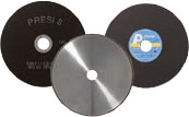
CUTTING
In other words, it is essential to avoid heating or any deformation of the metal that could lead to degradation of the material. Cutting is a fundamental step which conditions the further preparation and inspection of parts.

=> Clamping, i.e. holding the workpiece, is essential. If the workpiece is not held properly, the cut can be detrimental to the cut-off wheel, the workpiece and the machine.
CONSUMABLES
 |
STEELS «soft» |
STEELS «semi-hard» |
STEELS «hard» |
| Micro-cutting | UTW S Ø180 AOF II |
UTW S Ø180 AO AOF II |
UTW S Ø180 CBN |
| Medium-capacity cutting | A AOF II |
A AOF II |
S CBN |
| High-capacity cutting | A | AO | S CBN |
Table1: Choosing the right cut-off wheel type

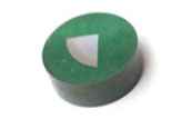
MOUNTING
=> Achieving good-quality mounting is essential to protect fragile materials and also to achieve good preparation results for polishing and future analysis.
Before mounting, the specimen should be deburred with coarse abrasive paper, for example, to remove any cutting burrs. Cleaning with ethanol (in an ultrasonic tank for even greater efficiency) is also possible. This allows the resin to adhere as well as possible to the sample and thus limits shrinkage (space between the resin and the sample).
If shrinkage persists, it can lead to problems during polishing. Abrasive grains may become lodged in this space and then be released at a later stage, thus creating a risk of pollution for the sample and the polishing surface. In this case, cleaning with an ultrasonic cleaner between each step is recommended.
There are two mounting options:
HOT MOUNTING
• Fully automatic hot-mounting press.
• Easy to use: memorisation, adjustment of processes and speed of execution make it a high-precision machine,
• The hot-mounting machine has 6 different mould diameters from 25.4-50mm.
+ POINT
COLD MOUNTING
• If the parts to be examined are fragile/sensitive to pressure
• If they have a complex geometry such as a honeycomb structure.
• If a large number of parts are to be mounted in series.
The cold process can be used with:
+ POINT
+ POINT
CONSUMABLES
 |
STEELS «soft» |
STEELS «semi-hardt» |
STEELS «hard» |
| Hot process | Phenolic Acrylic Allylic |
Hot epoxy Phenolic Acrylic Allylic |
Hot epoxy Phenolic Acrylic Allylic |
| Cold process | KM-U KM-B MA2+ 2S* |
KM-U KM-B IP 2S* |
KM-U KM-B IP 2S* |
Table 2: choosing the right mounting resin type
* Suitable for very large series

POLISHING
PRESI offers a wide range of manual and automatic polishing machines, with a wide choice of accessories, to cover all needs, from pre-polishing to super-finishing and polishing of single or series samples.
The MECATECH range of automatic polishers allows both manual and automatic polishing. With its advanced technologies, motor power from 750-1500 W, all the PRESI experience is concentrated in this very complete range. Whatever the sample number or size, MECATECH guarantees optimal polishing.
CONSUMABLES AND POLISHING RANGE
All the first steps of each range are called «levelling» and consist of removing material quickly to level the surface of the sample (and resin). Those given below are standard and can therefore be modified as required.
Supporting forces vary according to sample size, but in general the following applies: 1daN per 10mm mounting diameter for the pre-polishing steps (ex: Ø40mm = 4 daN) then reduce force by 0.5daN at each polishing step with an abrasive suspension.
RANGE N°1
| N° | Support | Suspension / Lubricant |
Platen Speed (RPM) |
Head Speed (RPM) |
Rotation direction platen / head |
Time |
| 1 | SiC P320 | Ø / Water | 300 | 150 | 1’ | |
| 2 | SiC 1200 | Ø / Water | 300 | 150 | 1’ | |
| 3 | RAM | 3μm LDP / Reflex Lub |
150 | 135 | 3’ | |
| 4 | NT | 1μm LDP / Reflex Lub |
150 | 135 | 1’ | |
| 5 | NT | Al2O3 n°3 / Water |
150 | 100 | 1’ |
RANGE N°2
| N° | Support | Suspension / Lubricant |
Platen Speed (RPM) |
Head Speed (RPM) |
Rotation direction platen / head |
Time |
| 1 | SiC P180 | Ø / Water | 300 | 150 | 1’ | |
| 2 | MED R | 9μm Super Abrasive / Ø |
150 | 135 | 3’ | |
| 3 | ADR II | 3μm LDP / Reflex Lub |
150 | 135 | 3’ | |
| 4 | NT | 1μm LDP / Reflex Lub |
150 | 135 | 1’ | |
| 5 | NT | Al2O3 n°3 / Water |
150 | 100 | 1’ |
RANGE N°3
| N° | Support | Suspension / Lubricant |
Platen Speed (RPM) |
Head Speed (RPM) |
Rotation direction platen / head |
Time |
| 1 | I-Max R 54μm |
Ø / Water | 300 | 150 | 3’ | |
| 2 | I-Max R 18μm |
Ø / Water | 300 | 150 | 3’ | |
| 3 | ADR II | 3μm LDP / Reflex Lub |
150 | 135 | 4’ | |
| 4 | NT | 1μm LDP / Reflex Lub |
150 | 135 | 1’ | |
| 5 | NT | Al2O3 n°3 / Water |
150 | 100 | 1’ |
 |
RANGE N°1 | RANGE N°2 | RANGE N°3 |
| Steels | All | All | “Semi-hard” “Hard” |
| Benefits | Flexible | Quick, reduced number of steps | • Long consumable service life • Optimised for large series • Excellent flatness |
Table N°3: choice of range
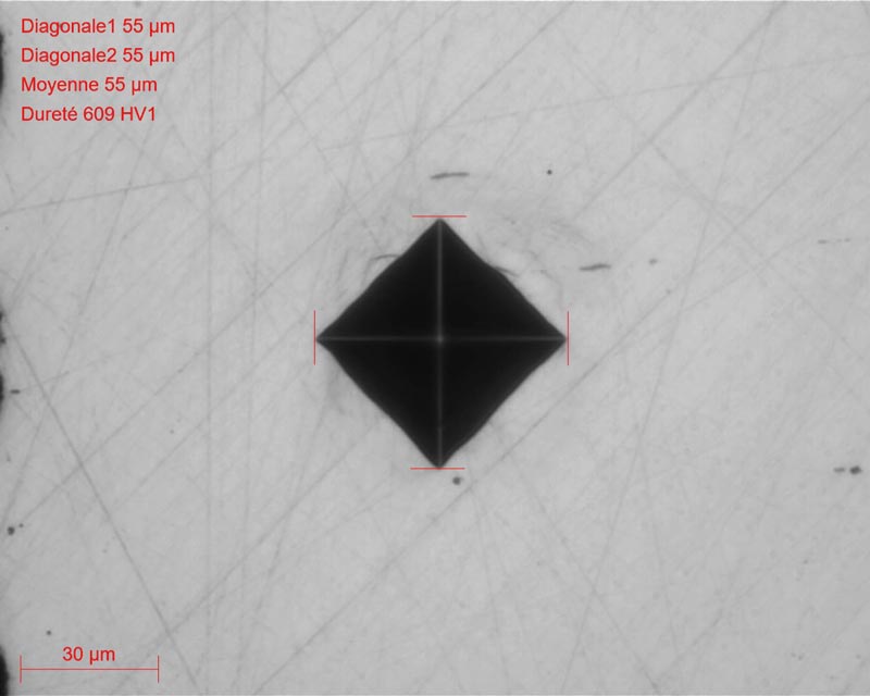
At the end of this preparation, the polished samples can be directly inspected without metallogra- phic etching. Metallographic etching is commonly done using the reagent Nital 4: a solution of 4% nitric acid and 96% ethanol. It can also be done with a Picral reagent: 4mg of picric acid and 100mL of ethanol. Etching creates differences in relief and/or colour between the different constituents and allows their inspection.

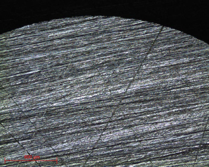
MICROSCOPY
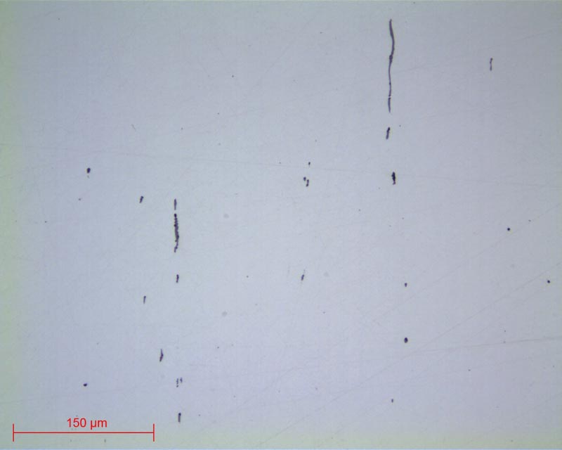
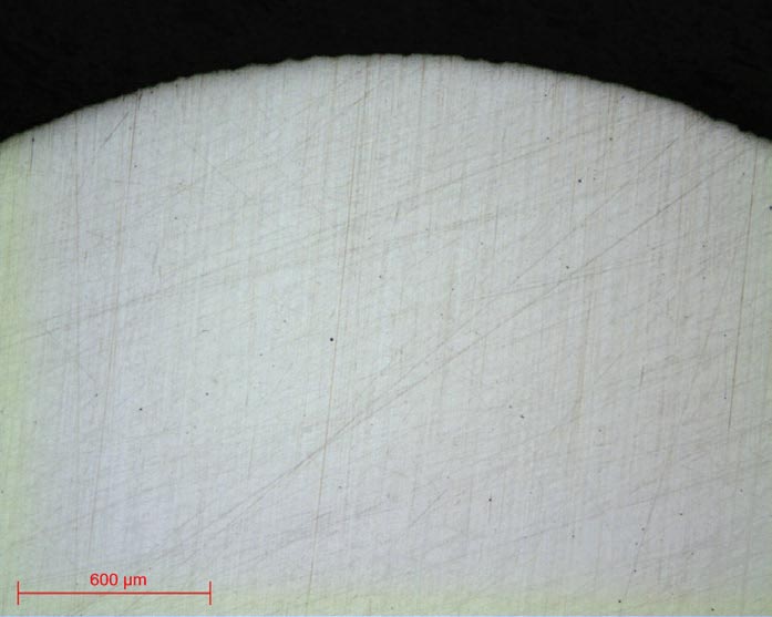
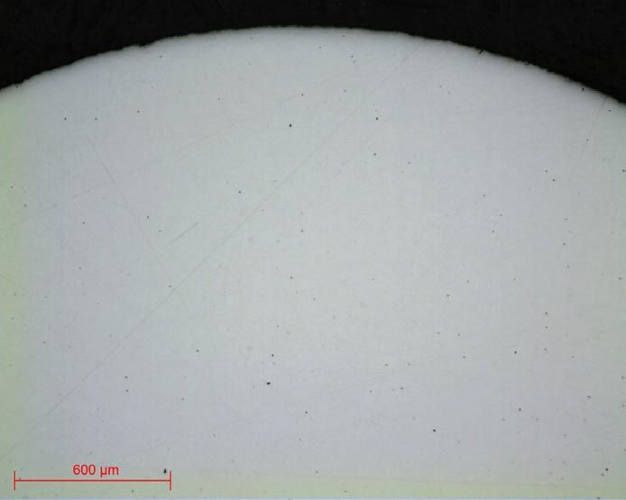
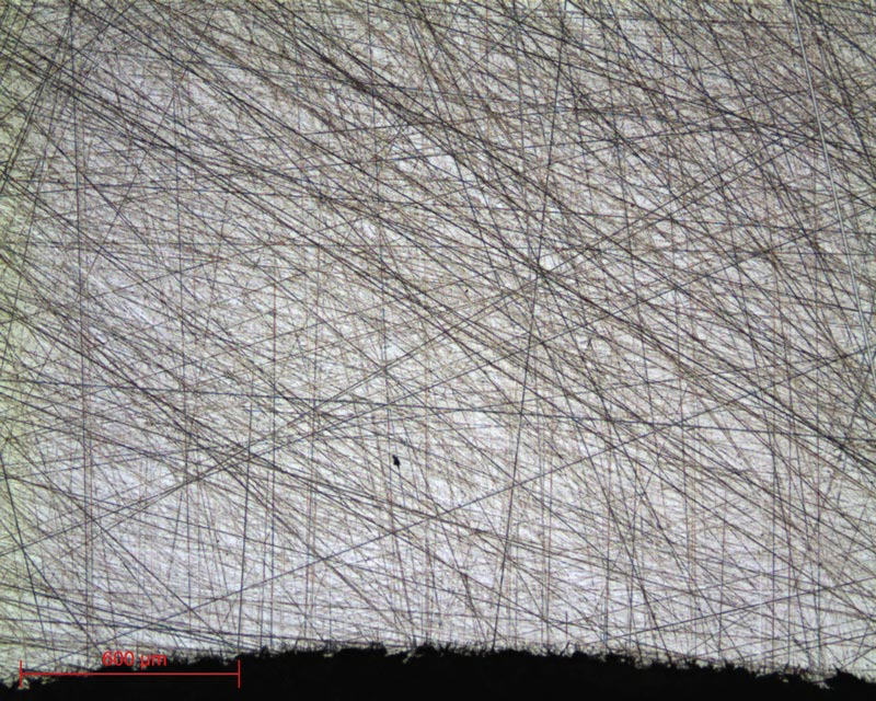
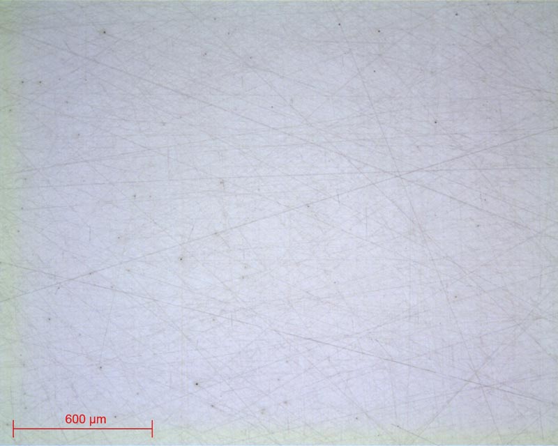
Observation of sulphide and silicate lens x20 type inclusions
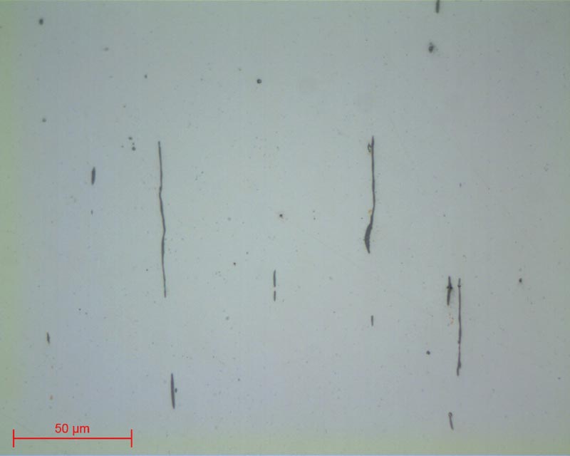
Observation of sulphide and silicate lens x50 type inclusions
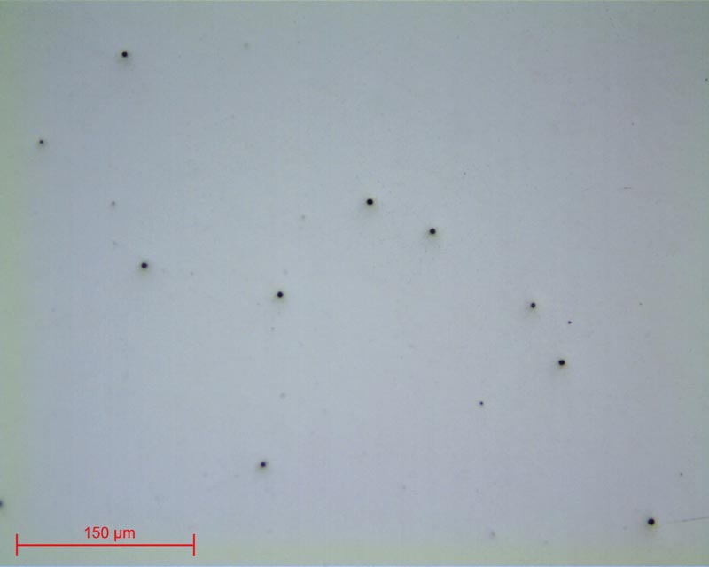
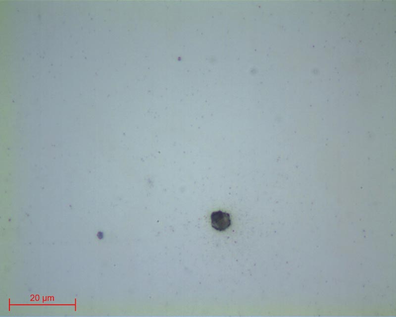
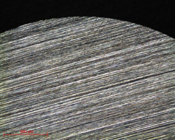
Micrographs 16 and 17:
Low carbon steel polished up to Al2O3 N°3
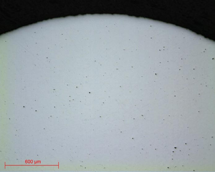
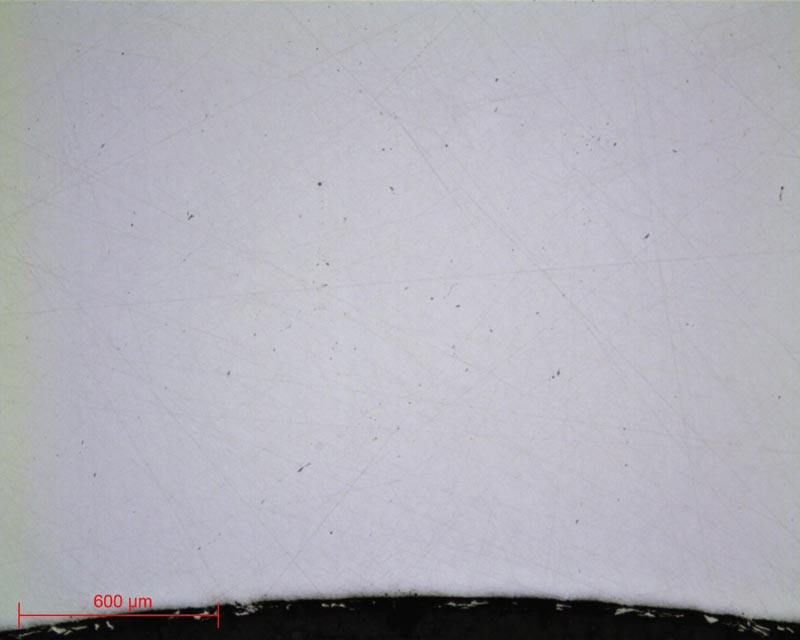
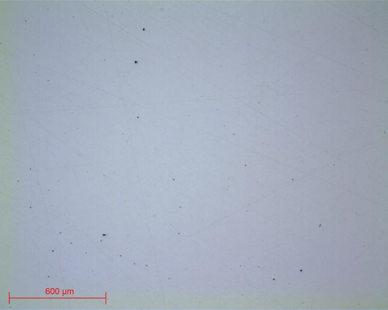
Observation of lens x20 and x100 oxide inclusions
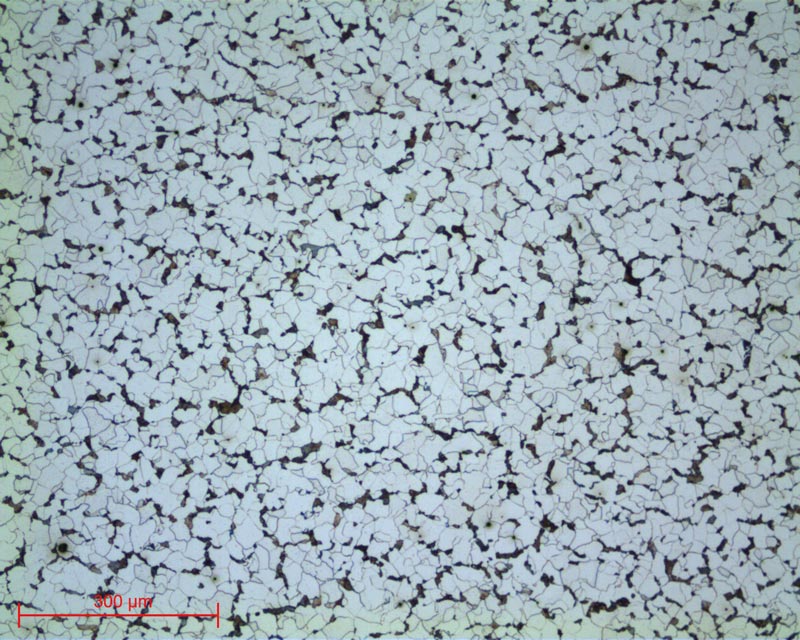
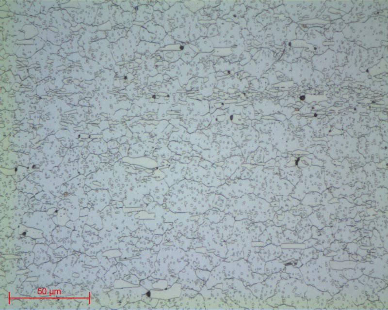
Micrographs 18 and 19:
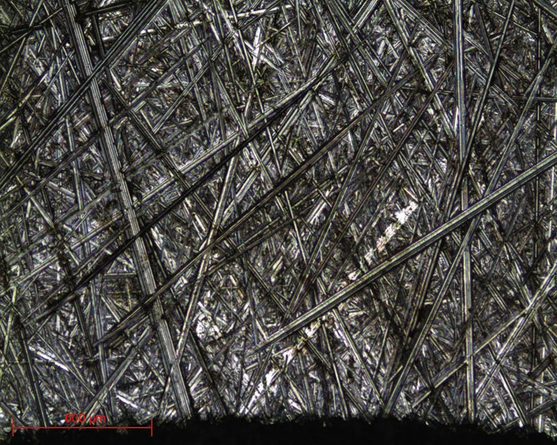
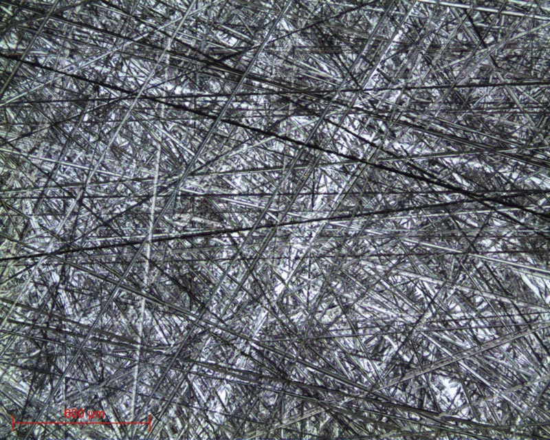
Hypoeutectoid Steel – Ferrite and Perlite etched with NITAL 4 lens x10 and x50
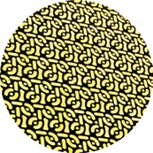
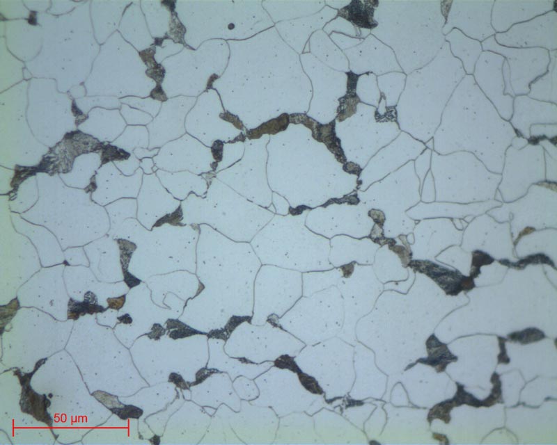
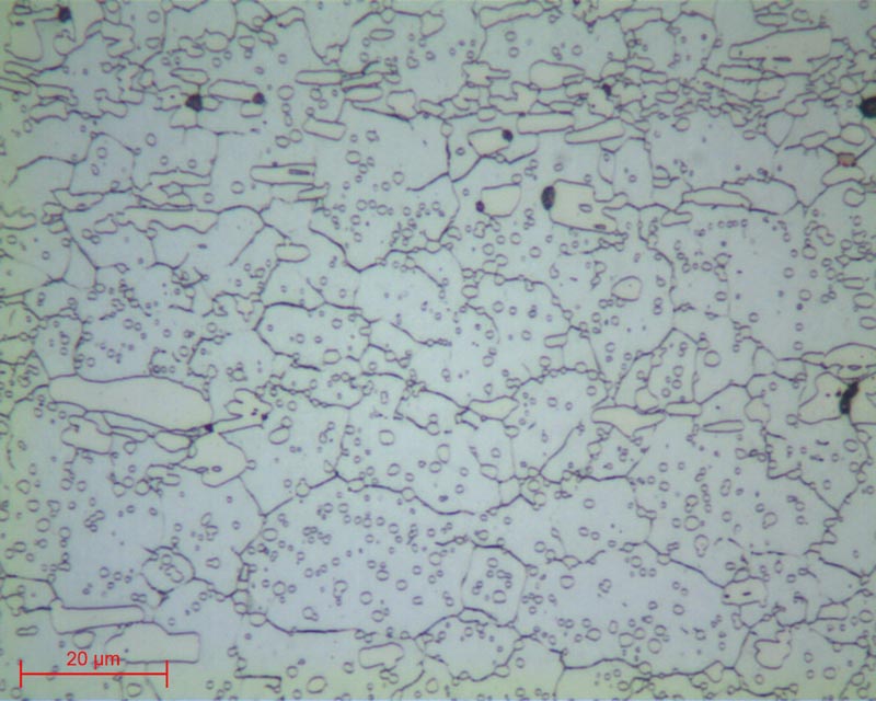
Micrographs 20 and 21:
Hypoeutectoid Steel – Ferrite and Perlite etched with NITAL 4 lens x10 and x100
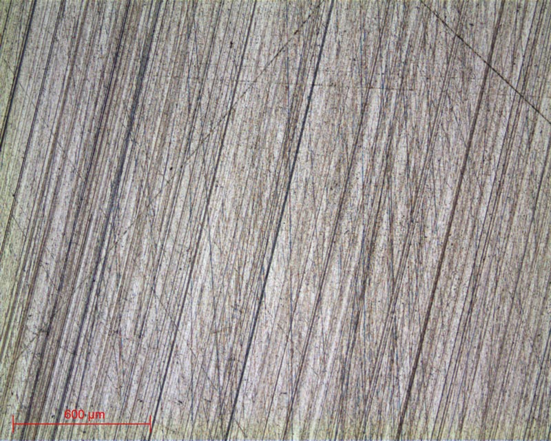
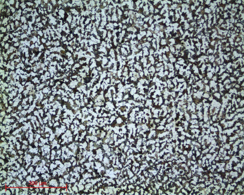
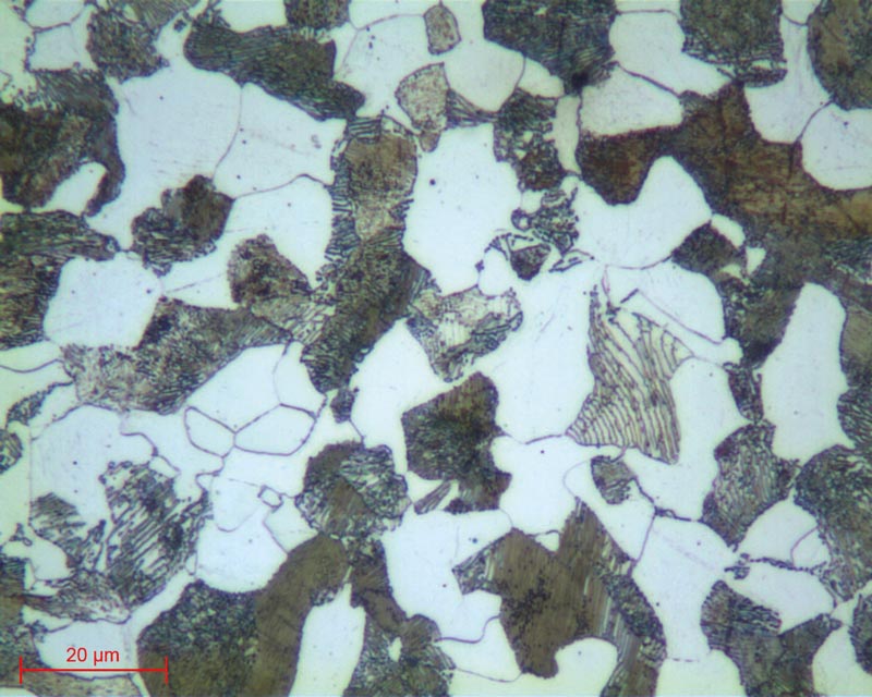
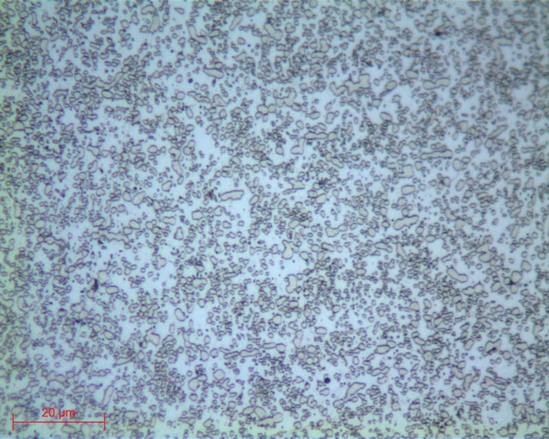
Micrographs 22 and 23:
Hypoeutectoid steel -Globular pearlite etched with NITAL 4 lens x50 and x100
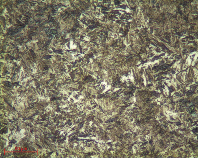
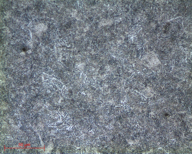
Etched with NITAL 4 lens x50
Etched with PICRAL lens x100
DOWNLOAD THE LAB'NOTE
Simply fill out the form below:
Discover our other Lab’Note:
- 3D printing quality control
- Hardened heat treatment control
- Medical device quality control
- Steel quality control
- Stainless steel quality control
- Cast iron quality control
- Copper alloy quality control
- Aluminum quality control
- Nickel quality control
- Titanium quality control
- Ceramic materials quality control
- Electronics quality control
- Precious metal quality control